Rostock MAX v2 Assembly Guide
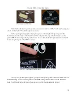
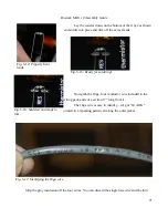
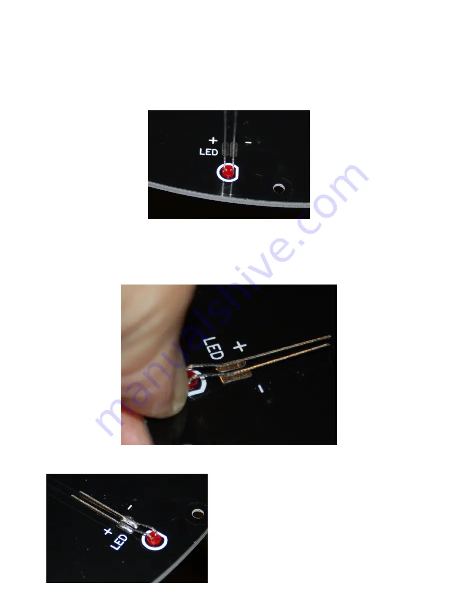
The flat side of the LED is the “cathode” or negative (-) side. You want to insert the diode in
the holes with the cathode lined up with the square pad as shown below. The silk screen also shows a
flatted outline that matches that of the LED base.
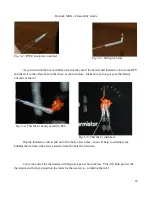
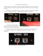
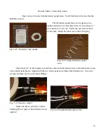
Bend the leads over so they are laying flat against the two solder pads as shown below and then
solder them into place. If you hold the rim of the LED in place with your thumbnail while you bend
the leads over, you'll end up with a nice “ramp” to the leads as shown in Fig. 5-10.
69
Fig. 5-9: LED orientation.
Fig. 5-10: LED ready to solder in.
Fig. 5-11: Leads soldered into place.
Содержание Rostock MAX v2
Страница 25: ...Rostock MAX v2 Assembly Guide Melamine Parts Sheet 1 25 ...
Страница 26: ...Rostock MAX v2 Assembly Guide Melamine Parts Sheet 2 Melamine Parts Sheet 3 26 ...
Страница 27: ...Rostock MAX v2 Assembly Guide Melamine Parts Sheet 4 27 ...
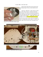
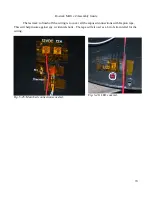
Страница 171: ...Rostock MAX v2 Assembly Guide 171 Fig 14 8 Spool holder support installed ...

