Rostock MAX v2 Assembly Guide
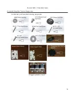
Before we can assemble the tower supports, you'll need to do a little prep work on the Stepper
Motor Mounts. Each mount will get two #6-32 nuts and one #4, 3/8” pan head machine screw.
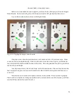
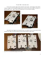
Lay out the mounts exactly as shown in the figure below.
The green arrows show the position where you'll install each #4, 3/8” pan head screw. These
screws are used as an alignment stop. When it comes time to set the towers in place, you'll slide the
tower down until the bottom strikes the head of the screw. This will guarantee that you've got all three
towers at the same height.
You may notice there's a bit of Scotch tape on the left-most mount. This was done because the
laser cut pocket was just a bit loose and I needed to be able to hold the nut in place until there was a
screw in it.
Note that the two mounts on the right are mirrors of one another. This was done on purpose.
The X and Y axis mounts are facing one another and if you don't mirror one of the mounts, you'll have
two that fit fine and one that won't fit at all. :)
56
Fig. 4-33: Prepping the stepper motor mounts.
Содержание Rostock MAX v2
Страница 25: ...Rostock MAX v2 Assembly Guide Melamine Parts Sheet 1 25 ...
Страница 26: ...Rostock MAX v2 Assembly Guide Melamine Parts Sheet 2 Melamine Parts Sheet 3 26 ...
Страница 27: ...Rostock MAX v2 Assembly Guide Melamine Parts Sheet 4 27 ...
Страница 171: ...Rostock MAX v2 Assembly Guide 171 Fig 14 8 Spool holder support installed ...

