Rostock MAX v2 Assembly Guide
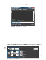
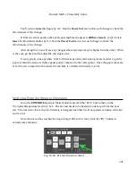
Now we can send the commands necessary to test the end stop switches. It's important that they
operate properly as they're used by the printer to determine the “home” position for the three towers.
Ensure that the end-stop adjustment screws are not in contact with the switches and then enter
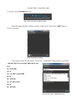
“M119” into the terminal input box and press the
ENTER
key.
The
M119
command instructs the RAMBo
board to return the current state of the three end
stop switches. The three switches are known as
“x_max”, “y_max”, and “z_max”. Each one
should have an “L” next to it as shown In Fig. 19-
15. If any of them show an “H”, check your
wiring to ensure that the switch is connected
properly at both ends. The printer will not operate
properly if any of the end-stop switches are
reporting “closed” when they're not.
An “L” next to each label indicates that all three end-stop switches have not been pressed. If
you see anything different, please check your wiring as mentioned previously! Now I want you to hold
down the switch lever for the X axis and re-send the
M119
command. You should see the
x_max
value
change to “H”. Do this for the Y and Z axes. This will ensure the end stop switches are functioning –
this is very important for the next step!
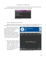
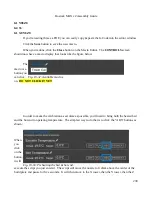
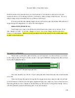
Click the
CONTROLS
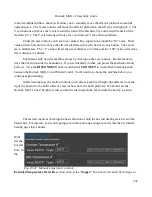
button to get to the screen where we'll perform the movement tests.
The next test we're going to perform involves making sure that the stepper motors on the towers
are wired correctly. Every once and a while we'll see a stepper motor with the connector wired
correctly, but the internal wiring is
backwards
. Maybe the elves that build stepper motors were having
a bad cookie day or something. Let's find out if you won a bad cookie motor!
229
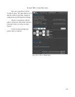
Fig. 19-16: Back to the Controls pane!
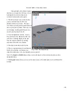
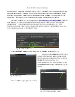
Fig. 19-17:Home Axes.
Содержание Rostock MAX v2
Страница 25: ...Rostock MAX v2 Assembly Guide Melamine Parts Sheet 1 25 ...
Страница 26: ...Rostock MAX v2 Assembly Guide Melamine Parts Sheet 2 Melamine Parts Sheet 3 26 ...
Страница 27: ...Rostock MAX v2 Assembly Guide Melamine Parts Sheet 4 27 ...
Страница 171: ...Rostock MAX v2 Assembly Guide 171 Fig 14 8 Spool holder support installed ...

