Rostock MAX v2 Assembly Guide
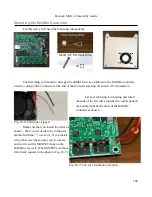
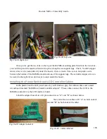
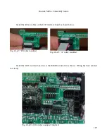
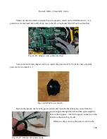
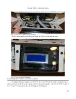
Make sure that the interface adapter board is properly seated on the RAMBo board – it is
possible to set the board down offset one row to the left or right and the LCD will not function.
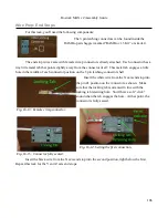
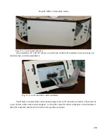
Your last task for this chapter will be to install the power switch. You'll of course need the
power switch to install it. :)
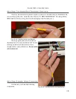
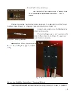
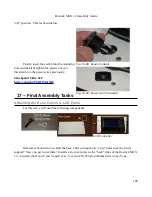
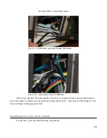
Remove the plastic nut from the power switch and route the black & green wires from the
power supply through the nut and then up through the
hole in the top plate. Attach the spade connectors to the
switch as shown in Fig. 16-48.
Make sure that you keep the power switch in the
198
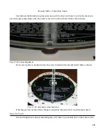
Fig. 16-46:The Power Switch.
Fig. 16-45: Adapter with cables attached.
Fig. 16-47: Nut over the power leads.
Содержание Rostock MAX v2
Страница 25: ...Rostock MAX v2 Assembly Guide Melamine Parts Sheet 1 25 ...
Страница 26: ...Rostock MAX v2 Assembly Guide Melamine Parts Sheet 2 Melamine Parts Sheet 3 26 ...
Страница 27: ...Rostock MAX v2 Assembly Guide Melamine Parts Sheet 4 27 ...
Страница 171: ...Rostock MAX v2 Assembly Guide 171 Fig 14 8 Spool holder support installed ...

