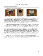
Rostock MAX v2 Assembly Guide
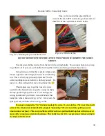
Once you've isolated the green & black
wires on the main ATX connector, go ahead and cut
them free of the connector as shown below.
DO NOT REMOVE THE ENTIRE ATX CONNECTOR. ONLY REMOVE THE WIRES
SHOWN.
Free the green & black wires from the rest of the wiring bundle. You can spin them into a loop
to get them out of your way or bundle them together with waxed lacing cord as I show below.
Using lacing cord like this is pretty simple and a
lot less expensive that using nylon wire ties in the long
run.
This is strictly my personal preference!
You're
under no obligation as a builder to do this yourself. I'm
just a bit...driven about what my wiring looks like.
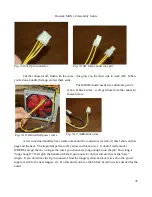
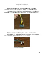
The simplest way to get the four wire pairs
needed for the heated bed is to grab a connector that's
already got them grouped for us. Look through the
wiring bundle until you find a connector bundle that
looks like what is shown in Fig. 3-15A. It may also be
split apart and look like what's in Fig. 3-15B.
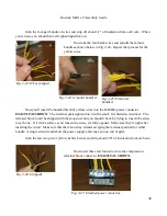
You may be tempted to “tin” the bare leads of the wires. Do not do this. The tinned lead will
prevent the compression terminal from properly “squashing” the wire (and thus getting a good,
broad contact surface). This can (and likely will) result in a spot heat build-up that will ruin one or
more of the compression terminal positions. This holds true for ALL compression terminal wiring in
the Rostock MAX v2 kit!
34
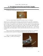
Fig. 3-11: Isolating the green & black wires.
Fig. 3-12: Wires cut free.
Содержание Rostock MAX v2
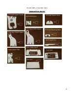
Страница 25: ...Rostock MAX v2 Assembly Guide Melamine Parts Sheet 1 25 ...
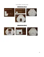
Страница 26: ...Rostock MAX v2 Assembly Guide Melamine Parts Sheet 2 Melamine Parts Sheet 3 26 ...
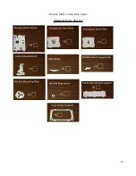
Страница 27: ...Rostock MAX v2 Assembly Guide Melamine Parts Sheet 4 27 ...
Страница 171: ...Rostock MAX v2 Assembly Guide 171 Fig 14 8 Spool holder support installed ...

