14-322
14-322
14.5.4. Load
The load state of each axis motor and the temperature of the encoder (Only the robot that corresponds to the
function of the encoder temperature) can be monitored.
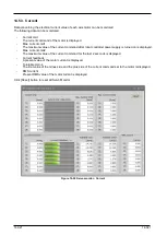
The following data can be monitored.
-
Axis load level
The present load ratio of each motor is displayed as an alarm level.
An overload error occurs when this value reaches 100%.
-
Max. axis load level
The maximum value of the axis load level after the robot controller power supply is turned on is displayed.
Click the [Reset] button to reset all Servo Monitors.
The robot controllers supporting the encoder temperature function are as follows.
Robot controller
Software version of the robot controller
CR800-D/CR800-R/ CR800-Q
All versions
CR750-D/CRnD-700
Ver.S3 or later
CR750-Q/CRnQ-700
Ver.R3 or later
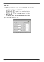
Figure 14-53 Servo monitor – Load
When the [Change] button is clicked, the following dialog for changing the ambient temperature is started up. The
ambient temperature parameter can be changed in this dialog.
Figure 14-54 Screen of change ambient temperature
Содержание 3F-14C-WINE
Страница 84: ...8 84 8 84 Figure 8 21 Parameter transfer procedure 1 2 2 ...
Страница 393: ...18 393 18 393 Figure 18 1 Starting the Oscillograph ...
Страница 413: ...18 413 18 413 Figure 18 24 Output to Robot program Selection ...
Страница 464: ...18 464 18 464 Figure 18 72 Starting the Tool automatic calculation ...
Страница 545: ...21 545 21 545 Figure 21 55 Hide display of user mechanism ...
Страница 624: ...24 624 24 624 Figure 24 4 Document output example ...

