21-606
21-606
Axis of symmetry
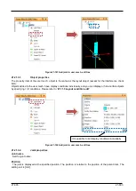
Assign the joint to the axis of the mechanism specified by the [Type] of the property of the user
mechanism.Please refer to “
21.9.2User mech. type and relationship to
J1 or J7
: Assign to J7 of Mech. # 1 (Robot)
Assign to J1 of Mech. number 2 or Mech. number 3
J2 or J8
: Assign to J8 of Mech. # 1 (Robot)
Assign to J2 of Mech. number 2 or Mech. number 3
J3
: Assign to J3 of Mech. number 2 or Mech. number 3
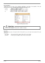
Figure 21-148 Target Axis of Joint
Axis value
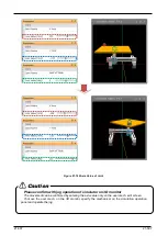
When entering a value or moving the knob of the slider bar, you can check the movement of the user
mechanism.
Axis rotation
: It can be set within the range of -180 to 180. The unit is [deg].
Axis linear
: It can be set in the range of -1000 to 1000. The unit is [mm].
J3 can not be assigned to the mech. number 1 (robot).
Caution
Содержание 3F-14C-WINE
Страница 84: ...8 84 8 84 Figure 8 21 Parameter transfer procedure 1 2 2 ...
Страница 393: ...18 393 18 393 Figure 18 1 Starting the Oscillograph ...
Страница 413: ...18 413 18 413 Figure 18 24 Output to Robot program Selection ...
Страница 464: ...18 464 18 464 Figure 18 72 Starting the Tool automatic calculation ...
Страница 545: ...21 545 21 545 Figure 21 55 Hide display of user mechanism ...
Страница 624: ...24 624 24 624 Figure 24 4 Document output example ...

