21-602
21-602
Except for the [
File Edit
] button, the rest of the operation is the same as the layout file,Please refet to
Edit user mech. file
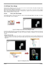
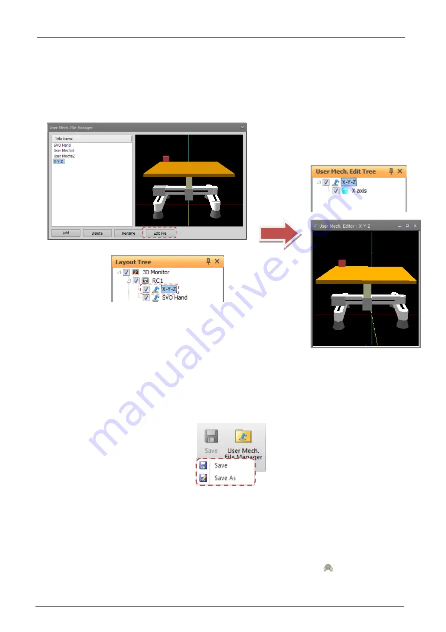
Double-click the selected edit file in the user mech. list, or click the [Edit] button to open the user mech. editing
dialog and display the edit tree. You can also open the user mech. editing screen by double-clicking the already
set user mech. in the layout tree.
Figure 21-139 Display Edit user mechanism
21.21.2.
Operation of editing user mechanism
The operation method is basically the same as the 3D monitor, refer to “
However, rotation of the viewpoint is possible only with the mouse operation unlike the 3D monitor.
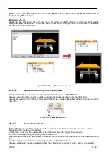
Use the [3D view] tab of the ribbon -> [User Mech. File] group -> [
Save
] / [
Save As
] button to save the user mech.
name file.
Figure 21-140 Save user mech. file
21.21.3.
User mech. edit tree
[
3D monitor
] in the layout tree is changed to the user mech. name that you set in the user mech. edit tree.
Add objects and create user mechanism.
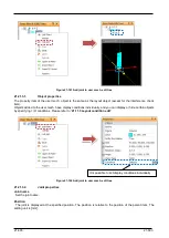
Joint is used for the part to be used as the axis of the mech. set in the [Type] of the property.
You can add joint by clicking [Add Joint] in the context menu.
When you add a joint, a red ball appears on the user mech. edit screen with the mark [
] in the user mech. edit
tree.
For other display contents and operation method, refer to “
However, display and operation related to robot, hand, robot parts, user mech., spline can not be executed.
Содержание 3F-14C-WINE
Страница 84: ...8 84 8 84 Figure 8 21 Parameter transfer procedure 1 2 2 ...
Страница 393: ...18 393 18 393 Figure 18 1 Starting the Oscillograph ...
Страница 413: ...18 413 18 413 Figure 18 24 Output to Robot program Selection ...
Страница 464: ...18 464 18 464 Figure 18 72 Starting the Tool automatic calculation ...
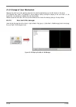
Страница 545: ...21 545 21 545 Figure 21 55 Hide display of user mechanism ...
Страница 624: ...24 624 24 624 Figure 24 4 Document output example ...

