21-565
21-565
21.11. Layout Object Display Settings
Display the 3D monitor and select the layout object whose display settings are to be changed in the layout tree.
The display settings of that layout object will be displayed at "Properties", and layout object related display
settings can be changed at respective items.
21.11.1.
Layout object display content settings
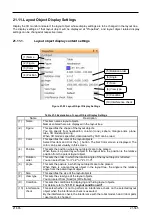
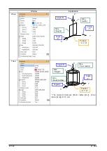
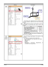
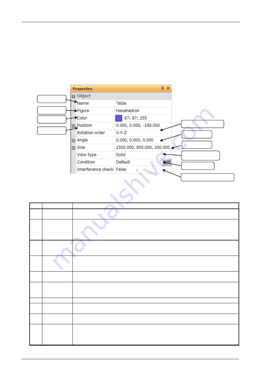
Figure 21-93 Layout Object Display Settings
Table 21-5 Explanation of Layout Object Display Settings
Name
Description
(1)
Name
This item names layout objects.
Names entered here are displayed in the layout tree.
(2)
Figure
This specifies the shape of the layout objects.
You can specify from hexahedron, column (cone), sphere, triangle prism, plane,
tube, 3D model and string.
When 3D model is specified, data created by CAD can be read.
(3)
Color
This specifies the color of the layout objects.
Select this item and click the [...] button. The Set Color screen is displayed. The
color can be set visually in this screen.
(4)
Position
This sets the position where layout objects are to be placed.
When there is a parent layout object in the layout tree, the position is the relative
position from the parent layout object.
(5)
Rotation
order
This sets the order in which the rotation angle of the layout object is reflected.
You can select from "X->Y->Z" or "Z->Y->X".
(6)
Angle
This sets the posture in which layout objects are to be placed.
When there is a parent layout object in the layout tree, the angle is the relative
angle from the parent layout object.
(7)
Size
This specifies the size of the layout objects.
(8)
View type
This sets the view type of the layout objects.
You can select from [Solid] or [Wire frame].
(9)
Condition
This sets the conditions for displaying and hiding layout objects.
For details, refer to
"21.11.3 Layout condition edit"
.
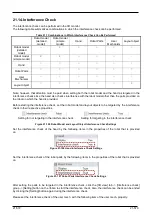
(10) Interference
check
This sets whether or not to perform an interference check on the selected layout
object when the interference check is executed.
By the interference check, the interference with the robot model, hand / robot parts
/ user mech. is checked.
(1) Name
(2) Figure
(3) Color
(4) Position
(7) Size
(6) Angle
(9) Condition
(8) View type
(5) Rotation order
(10) Interference check
Содержание 3F-14C-WINE
Страница 84: ...8 84 8 84 Figure 8 21 Parameter transfer procedure 1 2 2 ...
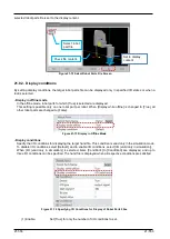
Страница 393: ...18 393 18 393 Figure 18 1 Starting the Oscillograph ...
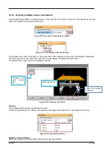
Страница 413: ...18 413 18 413 Figure 18 24 Output to Robot program Selection ...
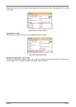
Страница 464: ...18 464 18 464 Figure 18 72 Starting the Tool automatic calculation ...
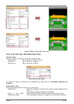
Страница 545: ...21 545 21 545 Figure 21 55 Hide display of user mechanism ...
Страница 624: ...24 624 24 624 Figure 24 4 Document output example ...

