13-225
13-225
13.3.6. User-defined area parameter
You can specify the region (cuboid) defined with two points in the robot XYZ coordinates and set the behavior for
when the robot enters this region.
Set the parameters while connected to the robot controller.
Double-click [Movement parameter] -> [User-defined area] under the [Parameter] item to be edited from the
project tree.
After you change a parameter value, you can rewrite the parameters in the robot controller by clicking the [Write]
button.
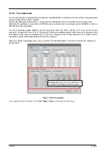
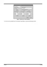
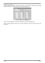
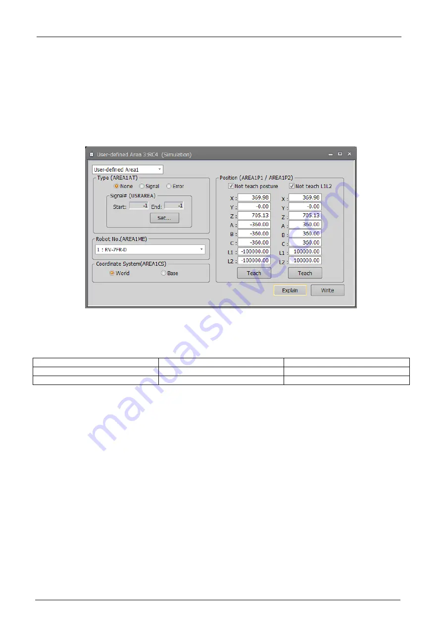
Figure 13-23 User-defined area parameter
The default is to select[Not teach posture][Not teach L1L2]. In this state, clicking each teaching button of AREA *
P1 and AREA * P2, the following values are set for robot attitude (A, B, C) and additional axes (L1, L2).
Table 13-7 [Not teach posture][Not teach L1L2] values taught when checkbox is enabled
AREA*P1
AREA*P2
Robot posture(A, B, C)
-360
360
Additional axes (L1,L2)
-100000
100000
If you want to teach the robot pusture and additional axes,please uncheck the checkbox.
Click the [Explain] button to refer to the parameter description.
13.3.7. Free plane limit parameters
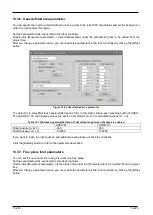
You can set the overrun limit for using the robot on a free plane.
Set the parameters while connected to the robot controller.
Double-click [Movement parameter] -> [Free plane limit] under the [Parameter] item to be edited from the project
tree.
After you change a parameter value, you can rewrite the parameters in the robot controller by clicking the [Write]
button.
Содержание 3F-14C-WINE
Страница 84: ...8 84 8 84 Figure 8 21 Parameter transfer procedure 1 2 2 ...
Страница 393: ...18 393 18 393 Figure 18 1 Starting the Oscillograph ...
Страница 413: ...18 413 18 413 Figure 18 24 Output to Robot program Selection ...
Страница 464: ...18 464 18 464 Figure 18 72 Starting the Tool automatic calculation ...
Страница 545: ...21 545 21 545 Figure 21 55 Hide display of user mechanism ...
Страница 624: ...24 624 24 624 Figure 24 4 Document output example ...


