23-617
23-617
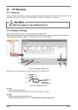
- Specifying condition1 / Specifying condition 1 and 2
Specifies 1 or 2 conditions and a signal value. The set value is applied when the set conditions are satisfied.
Figure 23-8 Specifying condition
(2) Signal type
Specify a Signal type.
Select from [PIO] (default), [CC-Link (Link Relay)] and [CC-Link (Link Register)].
The following items differ according to [Simulation operation] and [Signal type].
(3) Source / Destination / Reference side / Setting side
Select the signal copy source from robot, GX Simulator2 and GX Simulator3 devices.
You can select from [Project ID: name of project] (Only the number of projects is displayed), [GX Simulator2
A to D], and [GX Simulator3 #1 to 8].
GX Simulator2 is assigned to A to D in the order that it is started up. Startup GX Simulator2 so that the order
is matched.
GX Simulator3 is assigned to 1 to 8 in the order that it is started up. Startup GX Simulator3 so that the order
is matched.
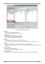
Figure 23-9 Items of Source / Destination / Reference side / Setting side
(4) Device
When [Source] / [Destination] / [Reference side] / [Setting side] is GX Simulator2, 3, select the device used in
the simulation. When it is robot, the device setting is fixed.
Table 23-1 Selectable Devices
[Signal Type]
[Source]/[Destination]/[Reference side]/[Setting side]
Robot
GX Simulator2, 3
[PIO]
[CC-Link(Link relay)]
[Bit device]
B (bit device)
SB (bit device)
L (bit device)
M (bit device)
[CC-Link(Link register)]
[Word device]
Содержание 3F-14C-WINE
Страница 84: ...8 84 8 84 Figure 8 21 Parameter transfer procedure 1 2 2 ...
Страница 393: ...18 393 18 393 Figure 18 1 Starting the Oscillograph ...
Страница 413: ...18 413 18 413 Figure 18 24 Output to Robot program Selection ...
Страница 464: ...18 464 18 464 Figure 18 72 Starting the Tool automatic calculation ...
Страница 545: ...21 545 21 545 Figure 21 55 Hide display of user mechanism ...
Страница 624: ...24 624 24 624 Figure 24 4 Document output example ...

