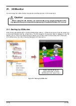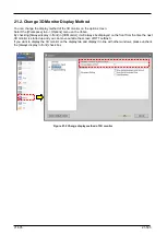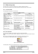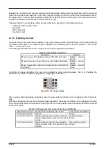
20-495
20-495
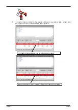
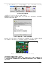
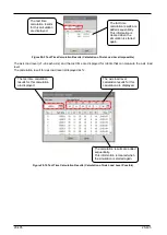
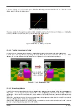
Figure 20-9 Tact Time Calculation Results (Calculation of Axis Load Level Impossible)
The axis load level (J1-J6 each axis) and the tact time are displayed for robots that can measure the axis load
level.
The calculation result for axis load level is displayed as %.
Figure 20-10 Tact Time Calculation Results (Calculation of Axis Load Level Possible)
The tact time
calculation results are
added sequentially.
This information is
cleared when the
simulation is started
again.
The tact time
calculation results
for this calculation
are displayed.
The calculation results are added
sequentially.
This information is cleared when
the simulation is started again.
The tact time calculation
results for this calculation
are displayed.
The axis load level
calculation results for this
calculation are displayed.
Содержание 3F-14C-WINE
Страница 84: ...8 84 8 84 Figure 8 21 Parameter transfer procedure 1 2 2 ...
Страница 393: ...18 393 18 393 Figure 18 1 Starting the Oscillograph ...
Страница 413: ...18 413 18 413 Figure 18 24 Output to Robot program Selection ...
Страница 464: ...18 464 18 464 Figure 18 72 Starting the Tool automatic calculation ...
Страница 545: ...21 545 21 545 Figure 21 55 Hide display of user mechanism ...
Страница 624: ...24 624 24 624 Figure 24 4 Document output example ...


