


14-313
14-313
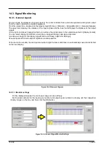
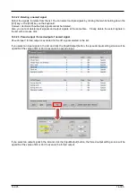
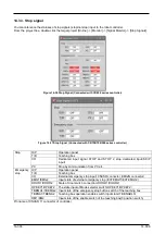
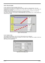
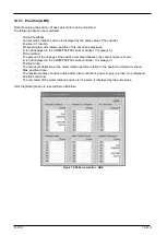
14.3.5. IO unit monitor
You can monitor the XY device variables of the IO unit.
From the project tree, double-click the target project [Online] -> [Monitor] -> [Signal Monitor] -> [IO unit].
The statuses of the input signals are displayed on the upper table, and the statuses of the output signals are
displayed on the lower table.
The signal values can display signed 16-bit integers or signed 32-bit integers in decimals or hexadecimals.
A continuous range for the display signals can be freely set in [Monitor setting].
This function is available in all versions of CR800-R/CR800-Q series controllers and in CR750-Q/CRnQ-700
controller Ver.R3 or later.
Figure 14-42 IO unit monitor
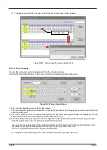
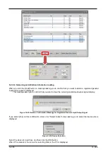
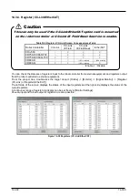
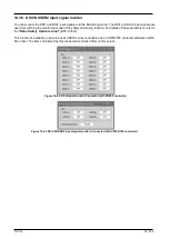
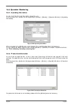
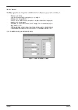
14.3.5.1. Monitor setting
Click the [Monitor setting] button. The PLC IO unit monitor setting screen is displayed.
Set the starting number of each device and indicate the number of lines to display also indicate the data size
display method when displaying signals.
After setting, click the [OK] button.
Figure 14-43 IO unit setting screen
Содержание 3F-14C-WINE
Страница 84: ...8 84 8 84 Figure 8 21 Parameter transfer procedure 1 2 2 ...
Страница 393: ...18 393 18 393 Figure 18 1 Starting the Oscillograph ...
Страница 413: ...18 413 18 413 Figure 18 24 Output to Robot program Selection ...
Страница 464: ...18 464 18 464 Figure 18 72 Starting the Tool automatic calculation ...
Страница 545: ...21 545 21 545 Figure 21 55 Hide display of user mechanism ...
Страница 624: ...24 624 24 624 Figure 24 4 Document output example ...