HV580L Series Frequency Inverter
99
over current protection of the AC drive.
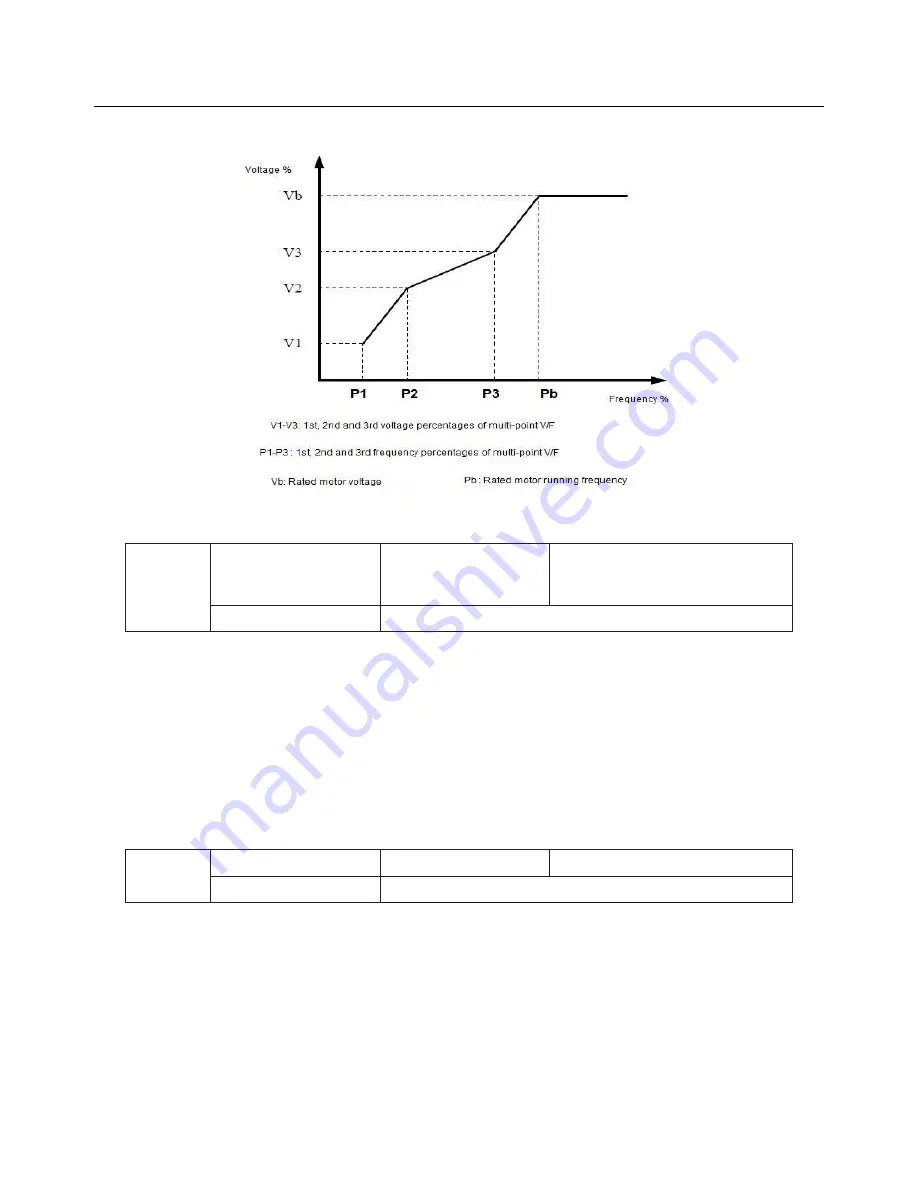
Figure 6-4 Setting of multi-point VF curve
P3-09
VF slip compensation
gain
Default
0.0%
Setting Range
0%
~
200.0%
This parameter is valid only for the asynchronous motor.
It can compensate the rotational speed slip of the asynchronous motor when the load of the motor increases,
stabilizing the motor speed in case of load change.
If this parameter is set to 100%, it indicates that the compensation when the motor bears rated load is the
rated motor slip. The rated motor slip is automatically obtained by the AC drive through calculation based on
the rated motor frequency and rated motor rotational speed in group P1.
Generally, if the motor rotational speed is different from the target speed, slightly adjust this parameter.
P3-10
VF over-excitation gain Default
64
Setting
0
~
200
During deceleration of the AC drive, over-excitation can restrain rise of the bus voltage, preventing the over
voltage fault. The larger the over-excitation is, the better the restraining result is.
Increase the over-excitation gain if the AC drive is liable to over voltage error during deceleration. However,
too large over-excitation gain may lead to an increase in the output current. Set P3-09 to a proper value in
actual applications.
Set the over-excitation gain to 0 in the applications where the inertia is small and the bus voltage will not rise
during motor deceleration or where there is a braking resistor.


