MAKING MODERN LIVING POSSIBLE
Operating Instructions
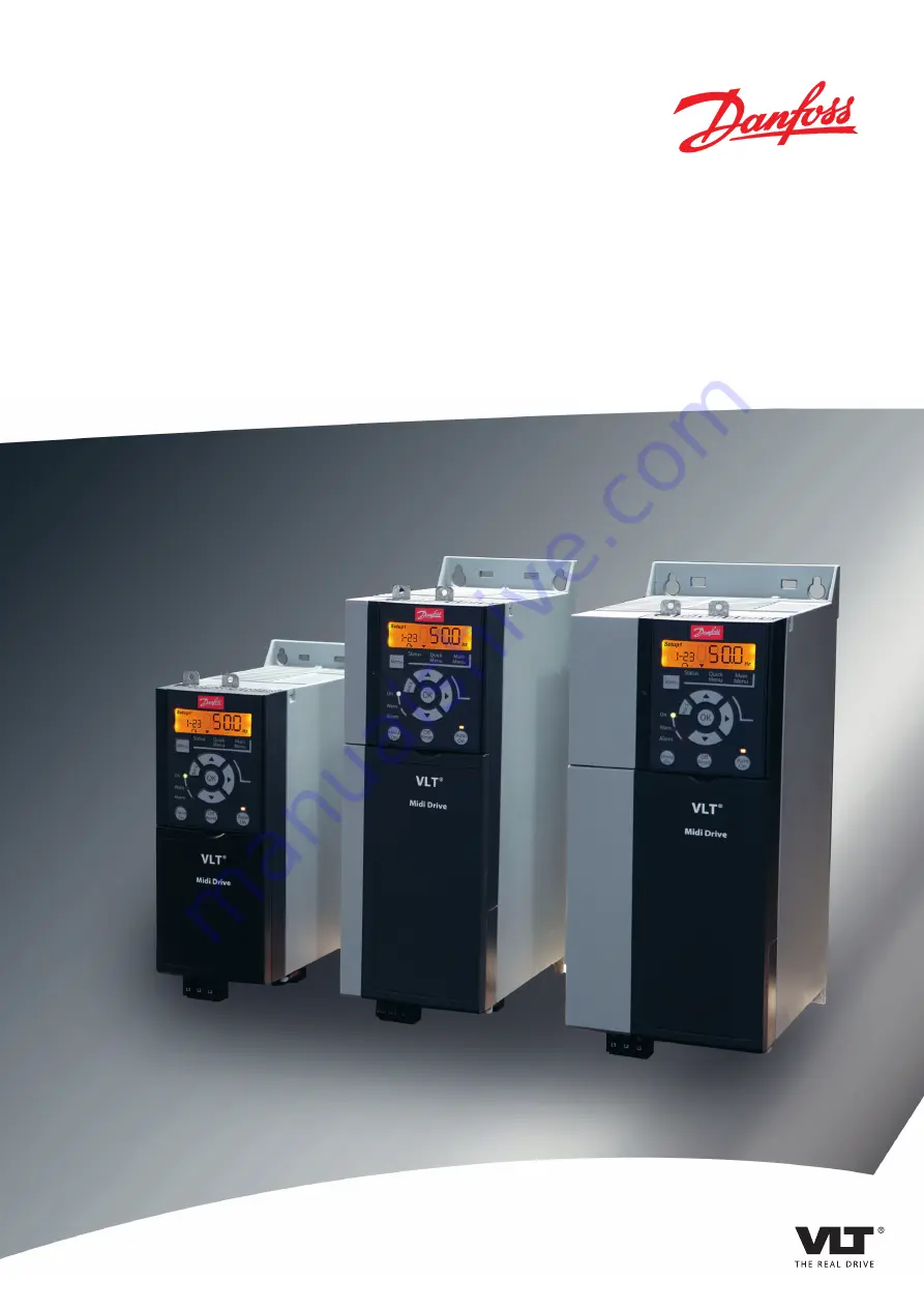
VLT
®
Midi Drive FC 280
vlt-drives.danfoss.com
Страница 1: ...MAKING MODERN LIVING POSSIBLE Operating Instructions VLT Midi Drive FC 280 vlt drives danfoss com...
Страница 2: ......
Страница 3: ...1 Safety Instructions 10 4 2 EMC compliant Installation 10 4 3 Grounding 10 4 4 Wiring Schematic 12 4 5 Access 14 4 6 Motor Connection 14 4 7 AC Mains Connection 15 4 8 Control Wiring 16 4 9 Installa...
Страница 4: ...and Alarms 43 8 5 Troubleshooting 45 9 Specifications 47 9 1 Electrical Data 47 9 2 Mains Supply 3 phase 48 9 3 Motor Output and Motor Data 48 9 4 Ambient Conditions 48 9 5 Cable Specifications 49 9...
Страница 5: ...response to system feedback or to remote commands from external controllers A power drive system consists of the frequency converter the motor and equipment driven by the motor System and motor status...
Страница 6: ...s and Dimensions 1 4 4 Safe Torque Off STO The VLT Midi Drive FC 280 frequency converter supports Safe Torque Off STO See chapter 9 9 Enclosure Sizes Power Ratings and Dimensions for details about the...
Страница 7: ...nverter is connected to AC mains DC supply or load sharing the motor may start at any time Unintended start during programming service or repair work can result in death serious injury or property dam...
Страница 8: ...rotating shafts and electrical equipment can result in death or serious injury Ensure that only trained and qualified personnel perform installation start up and maintenance Ensure that electrical wo...
Страница 9: ...storage are fulfilled Refer to chapter 9 4 Ambient Conditions for further details 3 2 Installation Environment NOTICE In environments with airborne liquids particles or corrosive gases ensure that the...
Страница 10: ...alled side by side in vertical or horizontal position The units do not require extra ventilation on the side 130BE615 10 Illustration 3 3 Side by side Installation CAUTION RISK OF OVERHEATING If IP21...
Страница 11: ...al springs 2 Metal clamps 3 Screws Illustration 3 4 Fasten the Horizontal Decoupling Plate with Screws 130BE481 10 1 2 1 Vertical decoupling plate 2 Screws Illustration 3 5 Fasten the Vertical Decoupl...
Страница 12: ...he installer must provide them See maximum fuse ratings in chapter 9 8 Fuses and Circuit Breakers Wire type and ratings All wiring must comply with local and national regulations regarding cross secti...
Страница 13: ...quipment see chapter 4 6 Motor Connection Use high strand wire to reduce electrical interference Do not use pigtails NOTICE POTENTIAL EQUALISATION Risk of electrical interference when the ground poten...
Страница 14: ...24 V NPN 0 V PNP 0 V PNP 24 V NPN 19 D IN 24 V NPN 0 V PNP 27 D IN OUT 24 V 0 V 0 V PNP 24 V NPN 29 D IN 24 V NPN 0 V PNP 0 V PNP 24 V NPN 33 D IN 32 D IN 38 D IN 37 D IN 95 P 5 00 2 1 ON DC R 89 BR 8...
Страница 15: ...2 Frequency converter 7 Motor 3 phase and PE 3 Output contactor generally not recommended 8 Mains single phase 3 phase and reinforced PE 4 Grounding rail PE 9 Control wiring 5 Cable shielding strippe...
Страница 16: ...r slip ring induction motor between the frequency converter and the motor Procedure 1 Strip a section of the outer cable insulation 2 Position the stripped cable under the cable clamp to establish mec...
Страница 17: ...units see Illustration 4 6 or to terminals L1 L2 and L3 for 3 phase units see Illustration 4 7 2 Depending on the configuration of the equipment connect the input power to the mains input terminals o...
Страница 18: ...eration Selectable for either digital input digital output or pulse output The default setting is digital input 29 Parameter 5 13 Ter minal 29 Digital Input 14 Jog Digital input 32 Parameter 5 14 Ter...
Страница 19: ...ues Digital input terminal 27 is designed to receive 24 V DC external interlock command When no interlock device is used wire a jumper between control terminal 12 recommended or 13 to terminal 27 The...
Страница 20: ...or basic serial communication set up select the following 1 Protocol type in parameter 8 30 Protocol 2 Frequency converter address in parameter 8 31 Address 3 Baud rate in parameter 8 32 Baud Rate Two...
Страница 21: ...bottom clearance is adequate to ensure proper air flow for cooling see chapter 3 3 Mounting Ambient conditions Check that requirements for ambient conditions are met Fusing and circuit breakers Check...
Страница 22: ...ing Power Apply power to the frequency converter using the following steps 1 Confirm that the input voltage is balanced within 3 If not correct the input voltage imbalance before proceeding Repeat thi...
Страница 23: ...roups parameters and within parameters or increasing decreasing parameter values Arrows can also be used for setting local reference 1 1 OK Press to access parameter groups or to enable a selection 1...
Страница 24: ...first parameter in the next parameter group for example move from parameter 0 03 Regional Settings 0 International to parameter 1 00 Configuration Mode 0 Open loop NOTICE During start up the LCP show...
Страница 25: ...XXX A 1 20 XXXX kW 1 22 XXXX V Motor nominal speed PM Motor Asynchronous Motor Motor power Motor voltage Motor Cont Rated Torque 1 26 XXXX 1 23 XXXX Hz Stator Resistance Motor frequency 1 25 XXXX rpm...
Страница 26: ...e or 3 times for array parameters to enter Main Menu or press Menu once to enter Status See Illustration 5 5 Illustration 5 6 and Illustration 5 7 for the principles of changing the value of continuou...
Страница 27: ...s OK to start editing 3 Change parameter value flashing 4 Press Back to cancel changes or OK to accept changes return to screen 2 5 Select a parameter within the group 6 Back Removes the value and sho...
Страница 28: ...eters 9 Alarm Log Shows a list of current warnings the last 10 alarms and the maintenance log Table 5 9 Legend to Illustration 5 8 Display Menu Keys C Navigation keys and indicator lights LEDs Navigat...
Страница 29: ...parameters press OK to select a parameter 4 Press to change the value of a parameter setting 5 Press to shift digit when a decimal parameter is in the editing state 6 Press OK to accept the change 7 P...
Страница 30: ...a is typically not available on the motor nameplate Run a complete AMA using parameter 1 29 Automatic Motor Adaptation AMA 1 Enable Complete AMA or enter the parameters manually 1 Parameter 1 30 Stato...
Страница 31: ...s Application Settings Low inertia applications ILoad IMotor 5 Increase the value for parameter 1 17 Voltage filter time const by factor 5 10 Reduce the value for parameter 1 14 Damping Gain Reduce th...
Страница 32: ...direction arrow is clockwise When parameter 1 06 Clockwise Direction is set to 1 Inverse counterclockwise a Verify that the motor turns counterclockwise b Verify that the LCP direction arrow is count...
Страница 33: ...the speed range 4 Remove the external run command 5 Check the sound and vibration levels of the motor to ensure that the system is working as intended If warnings or alarms occur see chapter 8 2 Warn...
Страница 34: ...Warning or alarm Energized1 Energized Yes2 No warnings or alarms De energized3 De energized No Warning alarm 68 Safe Stop De energized Energized No Alarm 188 STO Function Fault Energized De energized...
Страница 35: ...achine application consider the timing and distance for a coast to stop STO For more information regarding stop categories refer to EN 60204 1 6 2 Safe Torque Off Installation For motor connection AC...
Страница 36: ...7 or 38 terminates the SIL2 STO state potentially starting the motor Unexpected motor start may cause personal injuries or death Ensure that all safety measures are taken before reapplying 24 V DC sup...
Страница 37: ...a long time for the motor to stop 2b The customer relay activates if connected 2c Warning 68 Safe Stop W68 shows on the LCP if the LCP is mounted 2d If the LCP is not mounted Warning 68 Safe Stop W68...
Страница 38: ...in parameter 15 30 Alarm Log Error Code 3 Reapply 24 V supply to terminal 37 and verify that resetting the alarm is successful 4 Remove the 24 V supply for terminal 38 and verify that the LCP displays...
Страница 39: ...Category Cat 3 Diagnostic Coverage DC 60 Low Mean Time to Dangerous Failure MTTFd 2400 years High Performance Level PL d IEC 61508 IEC 61800 5 2 IEC 62061 Safety Integrity Level SIL2 Probability of Da...
Страница 40: ...rminal 12 and 27 are not connected set parameter 5 12 Terminal 27 Digital Input to 0 No operation Table 7 1 AMA with T27 Connected 7 1 2 Speed Parameters 130BE204 11 24 V D IN D IN D IN D IN D IN D IN...
Страница 41: ...21 Speed Up Parameter 5 14 T erminal 32 Digital Input 22 Speed Down Default value Notes comments Table 7 5 Speed Up Speed Down Start 18 Freeze ref 27 Speed up 29 Speed down 32 Speed Reference 130BB840...
Страница 42: ...0 Motor Feedback Loss Function 1 Warning Parameter 4 31 Motor Feedback Speed Error 50 Parameter 4 32 Motor Feedback Loss Timeout 5 s Parameter 7 00 S peed PID Feedback Source 1 24V encoder Parameter 5...
Страница 43: ...e abnormal condition is removed Alarm An alarm indicates a fault that requires immediate attention The fault always triggers a trip or trip lock Reset the frequency converter after an alarm Reset the...
Страница 44: ...e warning indicator light is yellow during a warning The alarm indicator light is red and flashing during an alarm 130BD062 10 D Hand On Reset Auto On OK On Warn Alarm Illustration 8 3 Status Indicato...
Страница 45: ...or terminals 17 Control word timeout X X No communication to frequency converter 25 Brake resistor short circuited X X Brake resistor is short circuited thus the brake function is disconnected 26 Brak...
Страница 46: ...re of the power card has exceeded the upper limit 80 Drive initialised to default value X All parameter settings are initialized to default settings 87 Auto DC braking X Occurs in IT mains when the fr...
Страница 47: ...signal Check if a reversing command is programmed for the terminal in parameter group 5 1 Digital inputs Deactivate reversing signal Wrong motor phase connection Change parameter 1 06 Clockwise Direct...
Страница 48: ...ter 1 position A to B B to C C to A If the imbalanced leg stays on same input terminal it is a problem with the unit Contact the supplier Motor current imbalance greater than 3 Problem with motor or m...
Страница 49: ...AC Frequency converter typical shaft output kW P4K0 4 P5K5 5 5 P7K5 7 5 P11K 11 P15K 15 P18K 18 5 P22K 22 IP20 K2 K2 K3 K4 K4 K5 K5 Output current Shaft output 4 5 5 7 5 11 15 18 5 22 Continuous 3x380...
Страница 50: ...0 Hz 5 Maximum imbalance temporary between mains phases 3 0 of rated supply voltage True power factor 0 9 nominal at rated load Displacement power factor cos near unity 0 98 Switching on input supply...
Страница 51: ...aximum motor cable length screened 50 m Maximum motor cable length unscreened 75 m Maximum cross section to control terminals flexible rigid wire 2 5 mm2 14 AWG Minimum cross section to control termin...
Страница 52: ...driven Maximum frequency at terminal 29 33 5 kHz open collector Minimum frequency at terminal 29 33 4 Hz Voltage level See the section on digital input Maximum voltage on input 28 V DC Input resistan...
Страница 53: ...ay outputs 1 Relay 01 01 03 NC 01 02 NO Maximum terminal load AC 1 1 on 01 02 NO Resistive load 250 V AC 3 A Maximum terminal load AC 15 1 on 01 02 NO Inductive load cos 0 4 250 V AC 0 2 A Maximum ter...
Страница 54: ...uit and overcurrent according to national international regulations NOTICE The recommendations do not cover branch circuit protection for UL Table 9 4 lists the recommended fuses and circuit breakers...
Страница 55: ...3 7 3 phase 380 480 V 0 37 0 55 0 75 1 1 1 5 2 2 3 4 5 5 7 5 11 15 18 5 22 Dimensions mm Height A 210 272 5 272 5 317 5 410 Width B 75 90 115 133 150 Depth C 168 168 168 245 245 Mounting holes a 198...
Страница 56: ...rotection LCP Local control panel MCT Motion control tool ns Synchronous motor speed PM N Nominal motor power PELV Protective extra low voltage PCB Printed circuit board PM Motor Permanent magnet moto...
Страница 57: ...tart Adjustments 1 71 Start Delay 1 72 Start Function 0 DC Hold delay time 1 DC Brake delay time 2 Coast delay time 3 Start speed cw 4 Horizontal operation 5 VVC clockwise 1 73 Flying Start 0 Disabled...
Страница 58: ...et Position Reached 172 Position Control Fault 173 Position Mech Brake 190 Safe Function active 193 Sleep Mode 194 Broken Belt Function 239 STO function fault 5 34 On Delay Digital Output 5 35 Off Del...
Страница 59: ...Start Select 8 54 Reversing Select 8 55 Set up Select 8 56 Preset Reference Select 8 57 Profidrive OFF2 Select 8 58 Profidrive OFF3 Select 8 7 BACnet 8 79 Protocol Firmware Version 8 8 FC Port Diagnos...
Страница 60: ...ink Temp 16 35 Inverter Thermal 16 36 Inv Nom Current 16 37 Inv Max Current 16 38 SL Controller State 16 39 Control Card Temp 16 5 Ref Feedb 16 50 External Reference 16 52 Feedback Unit 16 53 Digi Pot...
Страница 61: ...2 Pos PID Anti Windup 0 Disable 1 Enable 37 13 Pos PID Output Clamp 37 14 Pos Ctrl Source 0 DI 1 FieldBus 37 15 Pos Direction Block 0 No Blocking 1 Block Reverse 2 Block Forward 37 17 Pos Ctrl Fault B...
Страница 62: ...g 27 Derating 48 Digital input 17 Discharge time 5 Disconnect switch 20 Disposal instruction 4 E Electrical interference 11 EMC 49 EMC compliant installation 10 Encoder rotation 30 Energy efficiency 4...
Страница 63: ...rcurrent protection 10 P PELV 40 51 Potential equalization 11 Power connection 10 Power factor 4 19 Programming 17 26 27 Q Qualified personnel 5 Quick menu 22 26 R Recycling 4 Reference 26 Relay outpu...
Страница 64: ...44 Output terminal 20 Thermistor 40 Torque characteristic 48 Transient protection 4 U Unintended start 5 41 V Vibration 7 Voltage level 49 W Warning and alarm list 44 Wire size 10 Index VLT Midi Driv...
Страница 65: ...Index Operating Instructions MG07A102 Danfoss A S 11 2015 All rights reserved 63...
Страница 66: ...ucts already on order provided that such alterations can be made without subsequential changes being necessary in specifications already agreed All trademarks in this material are property of the resp...