E6581611
J-3
10
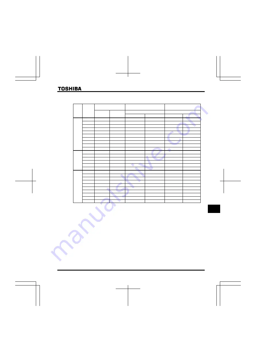
Selection of wiring devices
Input current (A)
Molded case circuit breaker (MCCB)
Earth leakage circuit breaker (ELCB)
Magnetic contactor (MC)
Note 2) Note 3)
Rated current (A)
Rated current (A)
Voltage
class
Applicable
motor
(kW)
Without
DCL
With DCL
Without DCL
With DCL
Without DCL
With DCL
0.4 3.6 1.8
5
5
20
20
0.75 6.3 3.4
10
5
20
20
1.5 11.1 6.5
15
10
20
20
2.2 14.9 9.2
20
15
20
20
4.0 23.8 15.9
30
20
32
20
5.5 35.6 21.5
50
30
50
32
7.5 46.1 28.9
60
40
60
32
11 63.1 41.5
100
60
80
50
15 82.1 55.7
125
75
100
60
3 phase
240V
class
18.5 89.1 70.0
125
100
100
80
0.2 3.4 2.0
5
5
20
20
0.4 5.9 4.0
10
5
20
20
0.75 10.0 7.6
15
10
20
20
1.5 17.8 14.6
30
20
32
20
2.2 24.0 20.1
30
30
32
32
1 phase
240V
class
3.0 24.0 23.6
30
30
32
32
0.4 2.1 0.9
5
5
20
20
0.75 3.6 1.8
5
5
20
20
1.5 6.4 3.4
10
5
20
20
2.2 8.8 4.8
15
10
20
20
4.0 13.7 8.3
20
15
20
20
5.5 20.7 11.2
30
15
32
20
7.5 26.6 15.1
40
20
32
20
11 36.6 21.7
50
30
50
32
15 47.7 29.0
60
40
60
32
3 phase
500V
class
Note 6)
18.5 52.7 36.3
75
50
60
50
The recommended molded case circuit breaker (MCCB) must be connected to primary side of each inverter to
protect the wiring system.
Note 1: Selections for use the Toshiba 4-pole standard motor with power supply voltage of 200V/ 400 - 50Hz.
Note 2: Be sure to attach a surge absorber to the exciting coil of the relay and the magnetic contactor.
Note 3: When using the auxiliary contacts 2a of the magnetic contactor MC for the control circuit, connect the
contacts 2a in parallel to increase reliability.
Note 4: When a motor is driven by commercial power supply using commercial power supply / inverter switching
circuit, use a magnetic contactor appropriated AC-3 class the motor rated current.
Note 5: Select an MCCB with a current breaking rating appropriate to the capacity of the power supply, because
short-circuit currents vary greatly depending on the capacity of the power supply and the condition of the
wiring system. The MCCB, MC and ELCB in this table were selected, on the assumption that a power
supply with a normal capacity would be used.
Note 6: For the operation and control circuits, regulate the voltage at 200V to 240V with a step-down transformer
for 500V class.
Note 7: In case of
aul
=
2
setting, be sure to select the wiring device for 1 rating up motor.
Note 8: Regarding influence of leakage current, refer to section 1.4.3.
Summary of Contents for Q9 Plus ASD
Page 5: ...TM Q9 Plus Bypass ASD Bypass Box INSTALLATION OPERATION MANUAL June 2013 DN 68251 000 ...
Page 61: ...Q9 PLUS ASD LOW VOLTAGE DRIVE ...
Page 65: ...S15 ASD LOW VOLTAGE DRIVE ...
Page 80: ...E6581611 iv 15 Warranty O 1 16 Disposal of the inverter P 1 ...
Page 429: ......
Page 430: ......


