


Section 24 Flash Memory
Rev. 1.00 Apr. 28, 2008 Page 779 of 994
REJ09B0452-0100
1. After boot mode is initiated, the bit rate of the SCI_1 is adjusted with that of the host.
2. Inquiry information about the size, configuration, start address, and support status of the user
MAT is transmitted to the host.
3. After inquiries have finished, all user MAT and user boot MAT are automatically erased.
4. When the program preparation notice is received, the state of waiting for program data is
entered. The start address of the programming destination and program data must be
transmitted after the programming command is transmitted. When programming is finished,
the start address of the programming destination must be set to H'FFFFFFFF and transmitted.
Then the state of waiting for program data is returned to the state of waiting for
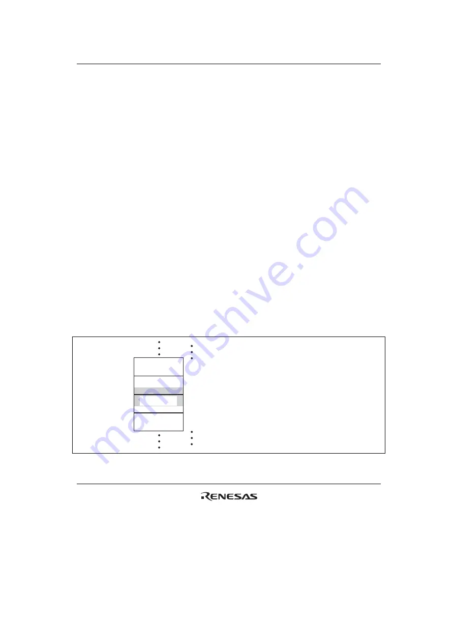
programming/erasing command. When reprogramming an erase block including an area on
which the programming end command is issued, erase the erase block. An example of the
erase block is shown in figure 24.9. When the erasure preparation notice is received, the state
of waiting for erase block data is entered. The erase block number must be transmitted after the
erasing command is transmitted. When the erasure is finished, the erase block number must be
set to H'FF and transmitted. Then the state of waiting for erase block data is returned to the
state of waiting for programming/erasing command. Erasure must be executed when the
specified block is programmed without a reset start after programming is executed in boot
mode. When programming can be executed by only one operation, all blocks are erased before
entering the state of waiting for programming/erasing command or another command. Thus, in
this case, the erasing operation is not required. The commands other than the
programming/erasing command perform sum check, blank check (erasure check), and memory
read of the user MAT and user boot MAT, and acquisition of current status information.
Memory read of the user MAT and user boot MAT can only read the data programmed after all
user MAT and user boot MAT have automatically been erased. No other data can be read.
EB5
EB6
EB7
EB8
Before reprogramming erase blocks EB6 and
EB7 on which the programming end command
is issued, erase the blocks (EB6 and EB7).
Programming
end area
Figure 24.9 Example of Erase Block Including Programmed Area
Summary of Contents for H8S/2100 Series
Page 2: ...Rev 1 00 Apr 28 2008 Page ii of xxvi...
Page 54: ...Section 1 Overview Rev 1 00 Apr 28 2008 Page 28 of 994 REJ09B0452 0100...
Page 92: ...Section 2 CPU Rev 1 00 Apr 28 2008 Page 66 of 994 REJ09B0452 0100...
Page 158: ...Section 5 Interrupt Controller Rev 1 00 Apr 28 2008 Page 132 of 994 REJ09B0452 0100...
Page 244: ...Section 8 8 Bit PWM Timer PWMU Rev 1 00 Apr 28 2008 Page 218 of 994 REJ09B0452 0100...
Page 330: ...Section 10 16 Bit Timer Pulse Unit TPU Rev 1 00 Apr 28 2008 Page 304 of 994 REJ09B0452 0100...
Page 416: ...Section 13 8 Bit Timer TMR Rev 1 00 Apr 28 2008 Page 390 of 994 REJ09B0452 0100...
Page 612: ...Section 18 I 2 C Bus Interface IIC Rev 1 00 Apr 28 2008 Page 586 of 994 REJ09B0452 0100...
Page 706: ...Section 20 LPC Interface LPC Rev 1 00 Apr 28 2008 Page 680 of 994 REJ09B0452 0100...
Page 752: ...Section 21 FSI Interface Rev 1 00 Apr 28 2008 Page 726 of 994 REJ09B0452 0100...
Page 774: ...Section 23 RAM Rev 1 00 Apr 28 2008 Page 748 of 994 REJ09B0452 0100...
Page 1008: ...Section 28 Electrical Characteristics Rev 1 00 Apr 28 2008 Page 982 of 994 REJ09B0452 0100...
Page 1020: ...Rev 1 00 Apr 28 2008 Page 994 of 994 REJ09B0452 0100...
Page 1023: ......
Page 1024: ...H8S 2117R Group Hardware Manual...


