29-84
MPC8260 PowerQUICC II UserÕs Manual
MOTOROLA
Part IV. Communications Processor Module
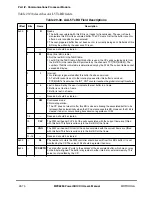
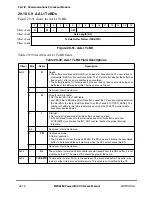
Table 29-45 describes UTOPIA slave mode signals.
29.12.2.1 UTOPIA Slave Multiple PHY Operation
In multiple PHY UTOPIA slave mode, cells are transferred using cell-level handshake as
deÞned by the UTOPIA level-2 standard. The user should write the ATM controller PHY
address in FPSMR[PHY ID].
29.12.2.2 UTOPIA Clocking Modes
The UTOPIA clock is generated by one of the MPC8260Õs baud-rate generators. The user
should assign one of the baud rate generators to supply the UTOPIA clock. See Chapter 15,
ÒCPM Multiplexing.Ó
Table 29-45. UTOPIA Slave Mode Signals
Signal
Description
TxDATA[0Ð15]
/[0Ð7]
Transmit data bus. Carries transmit data from the ATM controller to the master device. TxDATA[15]/
[7] is the msb, TxDATA[0] is the lsb.
TxSOC
Transmit start of cell. Asserted by an ATM controller as the Þrst byte of a cell is sent on the TxDATA
lines.
TxENB
Transmit enable. An input to the ATM controller. It is asserted by the UTOPIA master to signal the
slave to send data in the next TxCLK cycle.
TxCLAV
Transmit cell available. Asserted by the ATM controller to indicate it has a complete cell to transmit.
TxPRTY
Transmit parity. Asserted by the ATM controller. It is an odd parity bit over the TxDATA.
TxCLK
Transmit clock. Provides the synchronization reference for the TxDATA, TxSOC, TxENB, TxCLAV,
and TxPRTY signals. All of the above signals are sampled at low-to-high transitions of TxCLK.
TxADD[0Ð4]
Transmit address. Address bus from the master to the ATM controller used to select the appropriate
M-PHY device.
RxDATA[0Ð
15]/[0Ð7]
Receive data bus. Carries receive data from the master to the ATM controller. RxDATA[15]/[7] is the
msb, RxDATA[0] is the lsb.
RxSOC
Receive start of cell. Asserted by the master device whenever the Þrst byte of a cell is being received
on the RxDATA lines.
RxENB
Receive enable. Asserted by the master device to signal the slave to sample the RxDATA and
RxSOC signals.
RxCLAV
Receive cell available. Asserted by the ATM controller to indicate it can receive a complete cell.
RxPRTY
Receive parity. Asserted by the PHY device. It is an odd parity bit over the RxDATA[0Ð15]. If there is
a RxPRTY error and the receive parity check FPSMR[RxP] is enabled, the cell is discarded. See see
Section 29.13.2, ÒFCC Protocol-SpeciÞc Mode Register (FPSMR).Ó
RxCLK
Receive clock. Provides the synchronization reference for the RxDATA, RxSOC, RxENB, RxCLAV,
and RxPRTY signals. All the above signals are sampled at low-to-high transitions of RxCLK.
RxADD[0Ð4]
Receive address. Address bus from master to the ATM controller device used to select the
appropriate M-PHY device.
Summary of Contents for MPC8260 PowerQUICC II
Page 1: ...MPC8260UM D 4 1999 Rev 0 MPC8260 PowerQUICC II UserÕs Manual ª ª ...
Page 66: ...lxvi MPC8260 PowerQUICC II UserÕs Manual MOTOROLA ...
Page 88: ...1 18 MPC8260 PowerQUICC II UserÕs Manual MOTOROLA Part I Overview ...
Page 120: ...2 32 MPC8260 PowerQUICC II UserÕs Manual MOTOROLA Part I Overview ...
Page 138: ...Part II iv MPC8260 PowerQUICC II UserÕs Manual MOTOROLA Part II Configuration and Reset ...
Page 184: ...4 46 MPC8260 PowerQUICC II UserÕs Manual MOTOROLA Part II ConÞguration and Reset ...
Page 202: ...Part III vi MPC8260 PowerQUICC II UserÕs Manual MOTOROLA Part III The Hardware Interface ...
Page 266: ...8 34 MPC8260 PowerQUICC II UserÕs Manual MOTOROLA Part III The Hardware Interface ...
Page 382: ...10 106 MPC8260 PowerQUICC II UserÕs Manual MOTOROLA Part III The Hardware Interface ...
Page 392: ...11 10 MPC8260 PowerQUICC II UserÕs Manual MOTOROLA Part III The Hardware Interface ...
Page 430: ...Part IV viii MOTOROLA Part IV Communications Processor Module ...
Page 490: ...14 36 MPC8260 PowerQUICC II UserÕs Manual MOTOROLA Part IV Communications Processor Module ...
Page 524: ...17 10 MPC8260 PowerQUICC II UserÕs Manual MOTOROLA Part IV Communications Processor Module ...
Page 556: ...18 32 MPC8260 PowerQUICC II UserÕs Manual MOTOROLA Part IV Communications Processor Module ...
Page 584: ...19 28 MPC8260 PowerQUICC II UserÕs Manual MOTOROLA Part IV Communications Processor Module ...
Page 632: ...21 24 MPC8260 PowerQUICC II UserÕs Manual MOTOROLA Part IV Communications Processor Module ...
Page 652: ...22 20 MPC8260 PowerQUICC II UserÕs Manual MOTOROLA Part IV Communications Processor Module ...
Page 668: ...23 16 MPC8260 PowerQUICC II UserÕs Manual MOTOROLA Part IV Communications Processor Module ...
Page 758: ...27 28 MPC8260 PowerQUICC II UserÕs Manual MOTOROLA Part IV Communications Processor Module ...
Page 780: ...28 22 MPC8260 PowerQUICC II UserÕs Manual MOTOROLA Part IV Communications Processor Module ...
Page 874: ...29 94 MPC8260 PowerQUICC II UserÕs Manual MOTOROLA Part IV Communications Processor Module ...
Page 920: ...31 18 MPC8260 PowerQUICC II UserÕs Manual MOTOROLA Part IV Communications Processor Module ...
Page 980: ...A 4 MPC8260 PowerQUICC II UserÕs Manual MOTOROLA Appendixes ...
Page 1002: ...Index 22 MPC8260 PowerQUICC II UserÕs Manual MOTOROLA INDEX ...
Page 1006: ......


