MOTOROLA
Illustrations
xliii
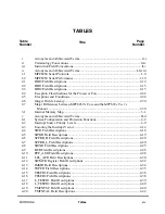
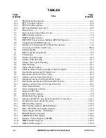
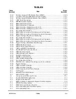
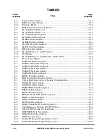
ILLUSTRATIONS
Figure
Number
Title
Page
Number
29-62
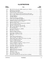
FCC Transmit Internal Rate Clocking ................................................................... 29-89
29-61
FCC Transmit Internal Rate Registers (FTIRRx).................................................. 29-89
29-63
COMM_INFO Field .............................................................................................. 29-90
29-64
AAL1 SRTS Generation Using External Logic .................................................... 29-91
29-65
AAL1 SRTS Clock Recovery Using External Logic ............................................ 29-92
30-1
Ethernet Frame Structure ......................................................................................... 30-1
30-2
Ethernet Block Diagram ......................................................................................... 30-3
30-3
Connecting the MPC8260 to Ethernet ..................................................................... 30-5
30-4
Ethernet Address Recognition Flowchart .............................................................. 30-16
30-5
FCC Ethernet Mode Registers (FPSMR) .............................................................. 30-20
30-6
Ethernet Event Register (FCCE)/Mask Register (FCCM) .................................... 30-22
30-7
Ethernet Interrupt Events Example........................................................................ 30-23
30-8
Fast Ethernet Receive Buffer (RxBD) ................................................................... 30-24
30-9
Ethernet Receiving Using RxBDs ......................................................................... 30-26
30-10
Fast Ethernet Transmit Buffer (TxBD).................................................................. 30-27
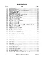
31-1
HDLC Framing Structure ........................................................................................ 31-2
31-2
HDLC Address Recognition Example..................................................................... 31-5
31-3
HDLC Mode Register (FPSMR) ............................................................................. 31-8
31-4
FCC HDLC Receiving Using RxBDs ................................................................... 31-10
31-5
FCC HDLC Receive Buffer Descriptor (RxBD)................................................... 31-11
31-6
FCC HDLC Transmit Buffer Descriptor (TxBD) ................................................. 31-12
31-7
HDLC Event Register (FCCE)/Mask Register (FCCM) ....................................... 31-14
31-8
HDLC Interrupt Event Example ............................................................................ 31-16
31-9
FCC Status Register (FCCS) ................................................................................. 31-16
32-1
In-Line Synchronization Pattern.............................................................................. 32-3
32-2
Sending Transparent Frames between MPC8260s .................................................. 32-4
33-1
SPI Block Diagram .................................................................................................. 33-1
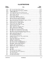
33-2
Single-Master/Multi-Slave Configuration ............................................................... 33-3
33-3
Multimaster Configuration ...................................................................................... 33-5
33-4
SPMODEÑSPI Mode Register............................................................................... 33-6
33-5
SPI Transfer Format with SPMODE[CP] = 0 ......................................................... 33-7
33-6
SPI Transfer Format with SPMODE[CP] = 1 ......................................................... 33-7
33-7
SPIE/SPIMÑSPI Event/Mask Registers................................................................. 33-9
33-8
SPCOMÑSPI Command Register ........................................................................ 33-10
33-9
RFCR/TFCRÑFunction Code Registers .............................................................. 33-12
33-10
SPI Memory Structure ........................................................................................... 33-13
33-11
SPI RxBD .............................................................................................................. 33-14
33-12
SPI TxBD............................................................................................................... 33-15
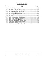
34-1
I
2
C Controller Block Diagram................................................................................. 34-1
34-2
I
2
C Master/Slave General Configuration ................................................................ 34-2
34-3
I
2
C Transfer Timing ................................................................................................ 34-3
34-4
I
2
C Master Write Timing......................................................................................... 34-4
34-5
I
2
C Master Read Timing ......................................................................................... 34-5
Summary of Contents for MPC8260 PowerQUICC II
Page 1: ...MPC8260UM D 4 1999 Rev 0 MPC8260 PowerQUICC II UserÕs Manual ª ª ...
Page 66: ...lxvi MPC8260 PowerQUICC II UserÕs Manual MOTOROLA ...
Page 88: ...1 18 MPC8260 PowerQUICC II UserÕs Manual MOTOROLA Part I Overview ...
Page 120: ...2 32 MPC8260 PowerQUICC II UserÕs Manual MOTOROLA Part I Overview ...
Page 138: ...Part II iv MPC8260 PowerQUICC II UserÕs Manual MOTOROLA Part II Configuration and Reset ...
Page 184: ...4 46 MPC8260 PowerQUICC II UserÕs Manual MOTOROLA Part II ConÞguration and Reset ...
Page 202: ...Part III vi MPC8260 PowerQUICC II UserÕs Manual MOTOROLA Part III The Hardware Interface ...
Page 266: ...8 34 MPC8260 PowerQUICC II UserÕs Manual MOTOROLA Part III The Hardware Interface ...
Page 382: ...10 106 MPC8260 PowerQUICC II UserÕs Manual MOTOROLA Part III The Hardware Interface ...
Page 392: ...11 10 MPC8260 PowerQUICC II UserÕs Manual MOTOROLA Part III The Hardware Interface ...
Page 430: ...Part IV viii MOTOROLA Part IV Communications Processor Module ...
Page 490: ...14 36 MPC8260 PowerQUICC II UserÕs Manual MOTOROLA Part IV Communications Processor Module ...
Page 524: ...17 10 MPC8260 PowerQUICC II UserÕs Manual MOTOROLA Part IV Communications Processor Module ...
Page 556: ...18 32 MPC8260 PowerQUICC II UserÕs Manual MOTOROLA Part IV Communications Processor Module ...
Page 584: ...19 28 MPC8260 PowerQUICC II UserÕs Manual MOTOROLA Part IV Communications Processor Module ...
Page 632: ...21 24 MPC8260 PowerQUICC II UserÕs Manual MOTOROLA Part IV Communications Processor Module ...
Page 652: ...22 20 MPC8260 PowerQUICC II UserÕs Manual MOTOROLA Part IV Communications Processor Module ...
Page 668: ...23 16 MPC8260 PowerQUICC II UserÕs Manual MOTOROLA Part IV Communications Processor Module ...
Page 758: ...27 28 MPC8260 PowerQUICC II UserÕs Manual MOTOROLA Part IV Communications Processor Module ...
Page 780: ...28 22 MPC8260 PowerQUICC II UserÕs Manual MOTOROLA Part IV Communications Processor Module ...
Page 874: ...29 94 MPC8260 PowerQUICC II UserÕs Manual MOTOROLA Part IV Communications Processor Module ...
Page 920: ...31 18 MPC8260 PowerQUICC II UserÕs Manual MOTOROLA Part IV Communications Processor Module ...
Page 980: ...A 4 MPC8260 PowerQUICC II UserÕs Manual MOTOROLA Appendixes ...
Page 1002: ...Index 22 MPC8260 PowerQUICC II UserÕs Manual MOTOROLA INDEX ...
Page 1006: ......

