30-6
MPC8260 PowerQUICC II UserÕs Manual
MOTOROLA
Part IV. Communications Processor Module
frame delimiter, and frame information are sent in that order; see Figure 30-1. In full-
duplex mode, since collisions are ignored, frame transmission maintains only the
interframe gap (96 serial clocks) regardless of CRS.
There is one internal buffer for out-of-sequence ßow control frames (in full-duplex Fast
Ethernet). When the Fast Ethernet controller is between frames, this buffer is polled if ßow
control is enabled. This buffer must contain the whole frame.
However, in half-duplex mode, the controller defers transmission if the line is busy (CRS
asserted). Before transmitting, the controller waits for carrier sense to become inactive, at
which point the controller determines if CRS remains negated for 60 serial clocks. If so, the
transmission begins after an additional 36 serial clocks (96 serial clocks after CRS
originally became negated).
If a collision occurs during the transmit frame, the Ethernet controller follows a speciÞed
backoff procedure and tries to retransmit the frame until the retry limit is reached. The
Ethernet controller stores at least the Þrst 64 bytes of data of the transmit frame in the dual-
port RAM, so that the data does not have to be retrieved from system memory in case of a
collision. This improves bus usage and latency if the backoff timer output requires an
immediate retransmission.
When the end of the current buffer is reached and TxBD[L] = 1, the FCS (32-bit CRC) bytes
are appended (if TxBD[TC] = 1), and TX_EN is negated. This notiÞes the PHY of the need
to generate the illegal Manchester encoding that signiÞes the end of an Ethernet frame.
Following the transmission of the FCS, the Ethernet controller writes the frame status bits
into the BD and clears TxBD[R]. When the end of the current buffer is reached and
TxBD[L] = 0 (a frame is comprised of multiple buffers), only TxBD[R] is cleared.
For both half- and full-duplex modes, an interrupt can be issued depending on TxBD[I].
The Ethernet controller then proceeds to the next TxBD in the table. In this way, the core
can be interrupted after each frame, after each buffer, or after a speciÞc buffer is sent. If
TxBD[PAD] = 1, the Ethernet controller pads short frames to the value of the minimum
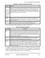
frame length register (MINFLR), described in Table 30-2.
To rearrange the transmit queue before the CP Þnishes sending all frames, issue a
GRACEFUL
STOP
TRANSMIT
command. This can be useful for transmitting expedited data
ahead of previously linked buffers or for error situations. When the
GRACEFUL
STOP
TRANSMIT
command is issued, the Ethernet controller stops immediately if no transmission
is in progress or continues transmission until the current frame either Þnishes or terminates
with a collision. When the Ethernet controller is given the
RESTART
TRANSMIT
command,
it resumes transmission. The Ethernet controller sends bytes least-signiÞcant nibble Þrst.
Summary of Contents for MPC8260 PowerQUICC II
Page 1: ...MPC8260UM D 4 1999 Rev 0 MPC8260 PowerQUICC II UserÕs Manual ª ª ...
Page 66: ...lxvi MPC8260 PowerQUICC II UserÕs Manual MOTOROLA ...
Page 88: ...1 18 MPC8260 PowerQUICC II UserÕs Manual MOTOROLA Part I Overview ...
Page 120: ...2 32 MPC8260 PowerQUICC II UserÕs Manual MOTOROLA Part I Overview ...
Page 138: ...Part II iv MPC8260 PowerQUICC II UserÕs Manual MOTOROLA Part II Configuration and Reset ...
Page 184: ...4 46 MPC8260 PowerQUICC II UserÕs Manual MOTOROLA Part II ConÞguration and Reset ...
Page 202: ...Part III vi MPC8260 PowerQUICC II UserÕs Manual MOTOROLA Part III The Hardware Interface ...
Page 266: ...8 34 MPC8260 PowerQUICC II UserÕs Manual MOTOROLA Part III The Hardware Interface ...
Page 382: ...10 106 MPC8260 PowerQUICC II UserÕs Manual MOTOROLA Part III The Hardware Interface ...
Page 392: ...11 10 MPC8260 PowerQUICC II UserÕs Manual MOTOROLA Part III The Hardware Interface ...
Page 430: ...Part IV viii MOTOROLA Part IV Communications Processor Module ...
Page 490: ...14 36 MPC8260 PowerQUICC II UserÕs Manual MOTOROLA Part IV Communications Processor Module ...
Page 524: ...17 10 MPC8260 PowerQUICC II UserÕs Manual MOTOROLA Part IV Communications Processor Module ...
Page 556: ...18 32 MPC8260 PowerQUICC II UserÕs Manual MOTOROLA Part IV Communications Processor Module ...
Page 584: ...19 28 MPC8260 PowerQUICC II UserÕs Manual MOTOROLA Part IV Communications Processor Module ...
Page 632: ...21 24 MPC8260 PowerQUICC II UserÕs Manual MOTOROLA Part IV Communications Processor Module ...
Page 652: ...22 20 MPC8260 PowerQUICC II UserÕs Manual MOTOROLA Part IV Communications Processor Module ...
Page 668: ...23 16 MPC8260 PowerQUICC II UserÕs Manual MOTOROLA Part IV Communications Processor Module ...
Page 758: ...27 28 MPC8260 PowerQUICC II UserÕs Manual MOTOROLA Part IV Communications Processor Module ...
Page 780: ...28 22 MPC8260 PowerQUICC II UserÕs Manual MOTOROLA Part IV Communications Processor Module ...
Page 874: ...29 94 MPC8260 PowerQUICC II UserÕs Manual MOTOROLA Part IV Communications Processor Module ...
Page 920: ...31 18 MPC8260 PowerQUICC II UserÕs Manual MOTOROLA Part IV Communications Processor Module ...
Page 980: ...A 4 MPC8260 PowerQUICC II UserÕs Manual MOTOROLA Appendixes ...
Page 1002: ...Index 22 MPC8260 PowerQUICC II UserÕs Manual MOTOROLA INDEX ...
Page 1006: ......


