MOTOROLA
Chapter 30. Fast Ethernet Controller
30-7
Part IV. Communications Processor Module
30.5 Ethernet Channel Frame Reception
The Ethernet receiver is designed to work with almost no core intervention and can perform
address recognition, CRC checking, short frame checking, maximum DMA transfer
checking, and maximum frame-length checking.
When the core enables the Ethernet receiver, it enters hunt mode when RX_DV is asserted
as long as COL remains negated (full-duplex mode ignores COL). In hunt mode, as data is
shifted into the receive shift register four bits at a time, the contents of the register are
compared to the contents of the SYN2 Þeld in the FCCÕs data synchronization register
(FDSR). When the registers match, the hunt mode is terminated and character assembly
begins.
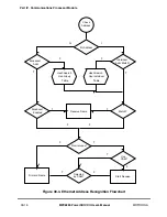
When the receiver detects the Þrst bytes of a frame, the Ethernet controller performs
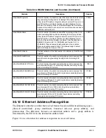
address recognition functions on the frame; see Section 30.12, ÒEthernet Address
Recognition.Ó The receiver can receive physical (individual), group (multicast), and
broadcast addresses. Because Ethernet receive frame data is not written to memory until the
internal address recognition algorithm is complete, bus usage is not wasted on frames not
addressed to this station. The receiver can also operate with an external CAM, in which case
frame reception continues normally, unless the CAM speciÞcally signals the frame to be
rejected. See Section 30.7, ÒCAM Interface.Ó
If an address is recognized, the Ethernet controller fetches the next RxBD and, if it is empty,
starts transferring the incoming frame to the RxBDÕs associated data buffer.
In half-duplex mode, if a collision is detected during the frame, the RxBDs associated with
this frame are reused. Thus, no collision frames are presented to the user except late
collisions, which indicate serious LAN problems. When the buffer has been Þlled, the
Ethernet controller clears RxBD[E] and generates an interrupt if RxBD[I] is set. If the
incoming frame is larger than the buffer, the Ethernet controller fetches the next RxBD in
the table; if it is empty, it continues receiving the rest of the frame.
The RxBD length is determined by MRBLR in the parameter RAM. The user should
program MRBLR to be at least 64 bytes. During reception, the Ethernet controller checks
for frames that are too short or too long. When the frame ends (CRS is negated), the receive
CRC Þeld is checked and written to the data buffer. The data length written to the last BD
in the Ethernet frame is the length of the entire frame, which enables the software to
recognize a frame-too-long condition.
If an external CAM is used (FPSMR
x
[CAM] = 1), the Ethernet controller adds the two
lower bytes of the CAM output at the end of each frame. Note that the data length does not
include these two bytes; that is, the extra two bytes could push the buffer length past
MRBLR.
When the receive frame is complete, the Ethernet controller sets RxBD[L], writes the other
frame status bits into the RxBD, and clears RxBD[E]. The Ethernet controller next
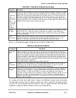
generates a maskable interrupt, indicating that a frame was received and is in memory. The
Summary of Contents for MPC8260 PowerQUICC II
Page 1: ...MPC8260UM D 4 1999 Rev 0 MPC8260 PowerQUICC II UserÕs Manual ª ª ...
Page 66: ...lxvi MPC8260 PowerQUICC II UserÕs Manual MOTOROLA ...
Page 88: ...1 18 MPC8260 PowerQUICC II UserÕs Manual MOTOROLA Part I Overview ...
Page 120: ...2 32 MPC8260 PowerQUICC II UserÕs Manual MOTOROLA Part I Overview ...
Page 138: ...Part II iv MPC8260 PowerQUICC II UserÕs Manual MOTOROLA Part II Configuration and Reset ...
Page 184: ...4 46 MPC8260 PowerQUICC II UserÕs Manual MOTOROLA Part II ConÞguration and Reset ...
Page 202: ...Part III vi MPC8260 PowerQUICC II UserÕs Manual MOTOROLA Part III The Hardware Interface ...
Page 266: ...8 34 MPC8260 PowerQUICC II UserÕs Manual MOTOROLA Part III The Hardware Interface ...
Page 382: ...10 106 MPC8260 PowerQUICC II UserÕs Manual MOTOROLA Part III The Hardware Interface ...
Page 392: ...11 10 MPC8260 PowerQUICC II UserÕs Manual MOTOROLA Part III The Hardware Interface ...
Page 430: ...Part IV viii MOTOROLA Part IV Communications Processor Module ...
Page 490: ...14 36 MPC8260 PowerQUICC II UserÕs Manual MOTOROLA Part IV Communications Processor Module ...
Page 524: ...17 10 MPC8260 PowerQUICC II UserÕs Manual MOTOROLA Part IV Communications Processor Module ...
Page 556: ...18 32 MPC8260 PowerQUICC II UserÕs Manual MOTOROLA Part IV Communications Processor Module ...
Page 584: ...19 28 MPC8260 PowerQUICC II UserÕs Manual MOTOROLA Part IV Communications Processor Module ...
Page 632: ...21 24 MPC8260 PowerQUICC II UserÕs Manual MOTOROLA Part IV Communications Processor Module ...
Page 652: ...22 20 MPC8260 PowerQUICC II UserÕs Manual MOTOROLA Part IV Communications Processor Module ...
Page 668: ...23 16 MPC8260 PowerQUICC II UserÕs Manual MOTOROLA Part IV Communications Processor Module ...
Page 758: ...27 28 MPC8260 PowerQUICC II UserÕs Manual MOTOROLA Part IV Communications Processor Module ...
Page 780: ...28 22 MPC8260 PowerQUICC II UserÕs Manual MOTOROLA Part IV Communications Processor Module ...
Page 874: ...29 94 MPC8260 PowerQUICC II UserÕs Manual MOTOROLA Part IV Communications Processor Module ...
Page 920: ...31 18 MPC8260 PowerQUICC II UserÕs Manual MOTOROLA Part IV Communications Processor Module ...
Page 980: ...A 4 MPC8260 PowerQUICC II UserÕs Manual MOTOROLA Appendixes ...
Page 1002: ...Index 22 MPC8260 PowerQUICC II UserÕs Manual MOTOROLA INDEX ...
Page 1006: ......


