MOTOROLA
Chapter 8. The 60x Bus
8-27
Part III. The Hardware Interface
following cycle. In case the external arbiter asserts DBG on the cycle in which TS
was asserted, PPC_ACR[DBGD] should be zero. Otherwise, PPC_ACR[DBGD]
should be set.
¥
External masters connected to the 60x bus must assert DBB only for the duration of
its data tenure. External masters should not use DBB to prevent other masters from
using the data bus after their data tenure has ended.
8.5.2 Data Streaming Mode
The MPC8260 supports a special data streaming mode that can improve bus performance
in some conditions. Generally, the bus protocol requires one idle cycle between any two
data tenures. This idle cycle is essential to prevent contention on the data bus when the
driver of the data is changing. However, when the driver on the data bus is the same for both
data tenures, this idle cycle may be omitted.
In data streaming mode, the MPC8260 omits the idle cycle where possible. MPC8260
applications often require data stream transfers of more than 4 x 64 bits. For example, the
ATM cellÕs payload is 6 x 64 bits. All this data is driven from a single device on the bus, so
data-streaming saves a cycle for such a transfer. When data-streaming mode is enabled,
transactions initiated by the core are not affected, while transactions initiated by other bus
masters within the chip omit the idle cycle if the data driver is the same. Note that data
streaming mode cannot be enabled when the MPC8260 is in 60x-compatible bus mode and
a device that uses DBB is connected to the bus. This restriction is due to the fact that a
MPC8260 for which data streaming mode is enabled may leave DBB asserted after the last
TA of a transaction and this is a violation of the strict bus protocol. The data streaming
mode is enabled by setting BCR[ETM].
8.5.3 Data Bus Transfers and Normal Termination
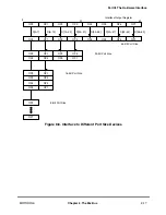
The data transfer signals include D[0Ð63] and DP[0Ð7]. For memory accesses, the data
signals form a 64-bit data path, D[0Ð63], for read and write operations.
The MPC8260 handles data transfers in either single-beat or burst operations. Single-beat
operations can transfer from 1 to 24 bytes of data at a time. Burst operations always transfer
eight words in four double-word beats. A burst transaction is indicated by the assertion of
TBST by the bus master. A transaction is terminated normally by asserting TA.
The three following signals are used to terminate the individual data beats of the data tenure
and the data tenure itself:
¥
TA indicates normal termination of data transactions. It must always be asserted on
the bus cycle coincident with the data that it is qualifying. It may be withheld by the
slave for any number of clocks until valid data is ready to be supplied or accepted.
¥
Asserting TEA indicates a nonrecoverable bus error event. Upon receiving a Þnal (or
only) termination condition, the MPC8260 always negates DBB for one cycle,
except when fast data bus grant is performed.
Summary of Contents for MPC8260 PowerQUICC II
Page 1: ...MPC8260UM D 4 1999 Rev 0 MPC8260 PowerQUICC II UserÕs Manual ª ª ...
Page 66: ...lxvi MPC8260 PowerQUICC II UserÕs Manual MOTOROLA ...
Page 88: ...1 18 MPC8260 PowerQUICC II UserÕs Manual MOTOROLA Part I Overview ...
Page 120: ...2 32 MPC8260 PowerQUICC II UserÕs Manual MOTOROLA Part I Overview ...
Page 138: ...Part II iv MPC8260 PowerQUICC II UserÕs Manual MOTOROLA Part II Configuration and Reset ...
Page 184: ...4 46 MPC8260 PowerQUICC II UserÕs Manual MOTOROLA Part II ConÞguration and Reset ...
Page 202: ...Part III vi MPC8260 PowerQUICC II UserÕs Manual MOTOROLA Part III The Hardware Interface ...
Page 266: ...8 34 MPC8260 PowerQUICC II UserÕs Manual MOTOROLA Part III The Hardware Interface ...
Page 382: ...10 106 MPC8260 PowerQUICC II UserÕs Manual MOTOROLA Part III The Hardware Interface ...
Page 392: ...11 10 MPC8260 PowerQUICC II UserÕs Manual MOTOROLA Part III The Hardware Interface ...
Page 430: ...Part IV viii MOTOROLA Part IV Communications Processor Module ...
Page 490: ...14 36 MPC8260 PowerQUICC II UserÕs Manual MOTOROLA Part IV Communications Processor Module ...
Page 524: ...17 10 MPC8260 PowerQUICC II UserÕs Manual MOTOROLA Part IV Communications Processor Module ...
Page 556: ...18 32 MPC8260 PowerQUICC II UserÕs Manual MOTOROLA Part IV Communications Processor Module ...
Page 584: ...19 28 MPC8260 PowerQUICC II UserÕs Manual MOTOROLA Part IV Communications Processor Module ...
Page 632: ...21 24 MPC8260 PowerQUICC II UserÕs Manual MOTOROLA Part IV Communications Processor Module ...
Page 652: ...22 20 MPC8260 PowerQUICC II UserÕs Manual MOTOROLA Part IV Communications Processor Module ...
Page 668: ...23 16 MPC8260 PowerQUICC II UserÕs Manual MOTOROLA Part IV Communications Processor Module ...
Page 758: ...27 28 MPC8260 PowerQUICC II UserÕs Manual MOTOROLA Part IV Communications Processor Module ...
Page 780: ...28 22 MPC8260 PowerQUICC II UserÕs Manual MOTOROLA Part IV Communications Processor Module ...
Page 874: ...29 94 MPC8260 PowerQUICC II UserÕs Manual MOTOROLA Part IV Communications Processor Module ...
Page 920: ...31 18 MPC8260 PowerQUICC II UserÕs Manual MOTOROLA Part IV Communications Processor Module ...
Page 980: ...A 4 MPC8260 PowerQUICC II UserÕs Manual MOTOROLA Appendixes ...
Page 1002: ...Index 22 MPC8260 PowerQUICC II UserÕs Manual MOTOROLA INDEX ...
Page 1006: ......

