4-27
MPC8260 PowerQUICC II UserÕs Manual
MOTOROLA
Part II. ConÞguration and Reset
13
LETM
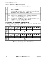
Local bus compatibility mode enable. See Section 8.4.3.8, ÒExtended Transfer Mode.Ó
1 Extended transfer mode is enable on the local bus.
0 Extended transfer mode is disabled in the local bus.
Note that if the local bus memory controller is conÞgured to work with read-modify-write parity,
LETM must be cleared.
14
EPAR
Even parity. Determines odd or even parity, Writing the memory with EPAR = 1 and reading the
memory with EPAR = 0 generates parity errors for testing.
15
LEPAR Local bus even parity. SpeciÞes odd or even parity in the local bus. Writing the memory with
LEPAR = 1 and reading the memory with LEPAR = 0 generates parity errors for testing.
16Ð18 NPQM Non PowerQUICC II master. IdentiÞes the type of bus masters which are connected to the
arbitration lines when the MPC8260 is in internal arbiter mode. Possible types are PowerQUICC II
master and non-PowerQUICC II master. This Þeld is related to the data pipelining bits (BRx[DR]) in
the memory controller. Because an external bus master that is not a MPC8260 cannot use the data
pipelining feature, the MPC8260, which controls the memory, needs to know when a non-
PowerQUICC II master is accessing the memory and handle the transaction differently.
NPQM[0] designates the type of master connected to the set of pins BR, BG, and DBG.
NPQM[1] designates the type of master connected to the set of pins EXT_BR2, EXT_BG2, and
EXT_DBG2.
NPQM[2] designates the type of master which is connected to the set of pins EXT_BR3, EXT_BG3
and EXT_DBG3
0 The bus master connected to the arbitration lines is a MPC8260.
1 The bus master connected to the arbitration lines is not a MPC8260.
16Ð20
Ñ
Reserved, should be cleared.
21
EXDD
External master delay disable. Generally, the MPC8260 adds one clock cycle delay for each
external master access to a region controlled by the memory controller. This occurs because the
external master drives the address on the external pins (compared to internal master, like
MPC8260Õs DMA, which drives the address on an internal bus in the chip). Thus, it is assumed that
an additional cycle is needed for the memory controllers banks to complete the address match.
However in some cases (when the bus is operated in low frequency), this extra cycle is not needed.
The user can disable the extra cycle by setting EXDD.
0 The memory controller inserts one wait state between the assertion of TS and the assertion of
CS when external master accesses an address space controlled by the memory controller.
1 The memory controller asserts CS on the cycle following the assertion of TS by external master
accessing an address space controlled by the memory controller.
22Ð26
Ñ
Reserved, should be cleared.
27
ISPS
Internal space port size. DeÞnes the port size of MPC8260Õs internal space region as seen to
external masters. Setting ISPS enables a 32-bit master to access MPC8260 internal space.
0 MPC8260 acts as a 64-bit slave to external masters accesses to its internal space.
1 MPC8260 acts as a 32-bit slave to external masters accesses to its internal space.
28Ð31
Ñ
Reserved, should be cleared.
Table 4-9. BCR Field Descriptions (Continued)
Bits
Name
Description
Summary of Contents for MPC8260 PowerQUICC II
Page 1: ...MPC8260UM D 4 1999 Rev 0 MPC8260 PowerQUICC II UserÕs Manual ª ª ...
Page 66: ...lxvi MPC8260 PowerQUICC II UserÕs Manual MOTOROLA ...
Page 88: ...1 18 MPC8260 PowerQUICC II UserÕs Manual MOTOROLA Part I Overview ...
Page 120: ...2 32 MPC8260 PowerQUICC II UserÕs Manual MOTOROLA Part I Overview ...
Page 138: ...Part II iv MPC8260 PowerQUICC II UserÕs Manual MOTOROLA Part II Configuration and Reset ...
Page 184: ...4 46 MPC8260 PowerQUICC II UserÕs Manual MOTOROLA Part II ConÞguration and Reset ...
Page 202: ...Part III vi MPC8260 PowerQUICC II UserÕs Manual MOTOROLA Part III The Hardware Interface ...
Page 266: ...8 34 MPC8260 PowerQUICC II UserÕs Manual MOTOROLA Part III The Hardware Interface ...
Page 382: ...10 106 MPC8260 PowerQUICC II UserÕs Manual MOTOROLA Part III The Hardware Interface ...
Page 392: ...11 10 MPC8260 PowerQUICC II UserÕs Manual MOTOROLA Part III The Hardware Interface ...
Page 430: ...Part IV viii MOTOROLA Part IV Communications Processor Module ...
Page 490: ...14 36 MPC8260 PowerQUICC II UserÕs Manual MOTOROLA Part IV Communications Processor Module ...
Page 524: ...17 10 MPC8260 PowerQUICC II UserÕs Manual MOTOROLA Part IV Communications Processor Module ...
Page 556: ...18 32 MPC8260 PowerQUICC II UserÕs Manual MOTOROLA Part IV Communications Processor Module ...
Page 584: ...19 28 MPC8260 PowerQUICC II UserÕs Manual MOTOROLA Part IV Communications Processor Module ...
Page 632: ...21 24 MPC8260 PowerQUICC II UserÕs Manual MOTOROLA Part IV Communications Processor Module ...
Page 652: ...22 20 MPC8260 PowerQUICC II UserÕs Manual MOTOROLA Part IV Communications Processor Module ...
Page 668: ...23 16 MPC8260 PowerQUICC II UserÕs Manual MOTOROLA Part IV Communications Processor Module ...
Page 758: ...27 28 MPC8260 PowerQUICC II UserÕs Manual MOTOROLA Part IV Communications Processor Module ...
Page 780: ...28 22 MPC8260 PowerQUICC II UserÕs Manual MOTOROLA Part IV Communications Processor Module ...
Page 874: ...29 94 MPC8260 PowerQUICC II UserÕs Manual MOTOROLA Part IV Communications Processor Module ...
Page 920: ...31 18 MPC8260 PowerQUICC II UserÕs Manual MOTOROLA Part IV Communications Processor Module ...
Page 980: ...A 4 MPC8260 PowerQUICC II UserÕs Manual MOTOROLA Appendixes ...
Page 1002: ...Index 22 MPC8260 PowerQUICC II UserÕs Manual MOTOROLA INDEX ...
Page 1006: ......

