MOTOROLA
Chapter 20. SCC UART Mode
20-13
Part IV. Communications Processor Module
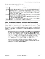
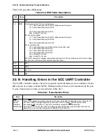
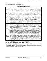
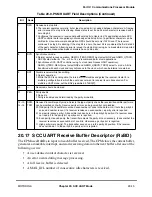
Reception errors are described in Table 20-8.
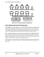
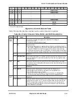
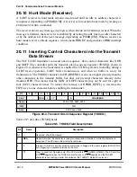
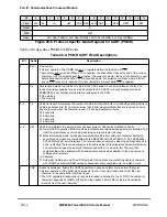
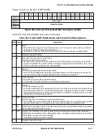
20.16 UART Mode Register (PSMR)
For UART mode, the SCC protocol-speciÞc mode register (PSMR) is called the UART
mode register. Many bits can be modiÞed while the receiver and transmitter are enabled.
Figure 20-6 shows the PSMR in UART mode.
Table 20-8. Reception Errors
Error
Description
Overrun
Occurs when the channel overwrites the previous character in the Rx FIFO with a new character, losing
the previous character. The channel then writes the new character to the buffer, closes it, sets RxBD[OV],
and generates an RX interrupt if not masked. In automatic multidrop mode, the receiver enters hunt mode
immediately.
CD Lost
during
Character
Reception
If this error occurs and the channel is using this pin to automatically control reception, the channel
terminates character reception, closes the buffer, sets RxBD[CD], and generates the RX interrupt if not
masked. This error has the highest priority. The last character in the buffer is lost and other errors are not
checked. In automatic multidrop mode, the receiver enters the hunt mode immediately.
Parity
When a parity error occurs, the channel writes the received character to the buffer, closes the buffer, sets
RxBD[PR], and generates the RX interrupt if not masked. The channel also increments the parity error
counter PAREC. In automatic multidrop mode, the receiver enters hunt mode immediately.
Noise
A noise error occurs when the three samples of a bit are not identical. When this error occurs, the channel
writes the received character to the buffer, proceeds normally, but increments the noise error counter
NOSEC. Note that this error does not occur in synchronous mode.
Idle
Sequence
Receive
If the UART is receiving data and gets an idle character (all ones), the channel begins counting
consecutive idle characters received. If MAX_IDL is reached, the buffer is closed and an RX interrupt is
generated if not masked. If no buffer is open, this event does not generate an interrupt or any status
information. The internal idle counter (IDLC) is reset every time a character is received. To disable the idle
sequence function, clear MAX_IDL.
Framing
The UART reports a framing errors when it receives a character with no stop bit, regardless of the mode.
The channel writes the received character to the buffer, closes it, sets RxBD[FR], generates the RX
interrupt if not masked, increments FRMEC, but does not check parity for this character. In automatic
multidrop mode, the receiver immediately enters hunt mode. If the UART allows data with no stop bits
(PSMR[RZS] = 1) when in synchronous mode (PSMR[SYN] = 1), framing errors are reported but
reception continues assuming the unexpected zero is the start bit of the next character; in this case, the
user may ignore a reported framing error until multiple framing errors occur within a short period.
Break
Sequence
When the Þrst break sequence is received, the UART increments the break error counter BRKEC. It
updates BRKLN when the sequence completes. After the Þrst 1 is received, the UART sets SCCE[BRKE],
which generates an interrupt if not masked. If the UART is receiving characters when it receives a break,
it closes the Rx buffer, sets RxBD[BR], and sets SCCE[RX], which can generate an interrupt if not
masked. If PSMR[RZS] = 1 when the UART is in synchronous mode, a break sequence is detected after
two successive break characters are received.
Summary of Contents for MPC8260 PowerQUICC II
Page 1: ...MPC8260UM D 4 1999 Rev 0 MPC8260 PowerQUICC II UserÕs Manual ª ª ...
Page 66: ...lxvi MPC8260 PowerQUICC II UserÕs Manual MOTOROLA ...
Page 88: ...1 18 MPC8260 PowerQUICC II UserÕs Manual MOTOROLA Part I Overview ...
Page 120: ...2 32 MPC8260 PowerQUICC II UserÕs Manual MOTOROLA Part I Overview ...
Page 138: ...Part II iv MPC8260 PowerQUICC II UserÕs Manual MOTOROLA Part II Configuration and Reset ...
Page 184: ...4 46 MPC8260 PowerQUICC II UserÕs Manual MOTOROLA Part II ConÞguration and Reset ...
Page 202: ...Part III vi MPC8260 PowerQUICC II UserÕs Manual MOTOROLA Part III The Hardware Interface ...
Page 266: ...8 34 MPC8260 PowerQUICC II UserÕs Manual MOTOROLA Part III The Hardware Interface ...
Page 382: ...10 106 MPC8260 PowerQUICC II UserÕs Manual MOTOROLA Part III The Hardware Interface ...
Page 392: ...11 10 MPC8260 PowerQUICC II UserÕs Manual MOTOROLA Part III The Hardware Interface ...
Page 430: ...Part IV viii MOTOROLA Part IV Communications Processor Module ...
Page 490: ...14 36 MPC8260 PowerQUICC II UserÕs Manual MOTOROLA Part IV Communications Processor Module ...
Page 524: ...17 10 MPC8260 PowerQUICC II UserÕs Manual MOTOROLA Part IV Communications Processor Module ...
Page 556: ...18 32 MPC8260 PowerQUICC II UserÕs Manual MOTOROLA Part IV Communications Processor Module ...
Page 584: ...19 28 MPC8260 PowerQUICC II UserÕs Manual MOTOROLA Part IV Communications Processor Module ...
Page 632: ...21 24 MPC8260 PowerQUICC II UserÕs Manual MOTOROLA Part IV Communications Processor Module ...
Page 652: ...22 20 MPC8260 PowerQUICC II UserÕs Manual MOTOROLA Part IV Communications Processor Module ...
Page 668: ...23 16 MPC8260 PowerQUICC II UserÕs Manual MOTOROLA Part IV Communications Processor Module ...
Page 758: ...27 28 MPC8260 PowerQUICC II UserÕs Manual MOTOROLA Part IV Communications Processor Module ...
Page 780: ...28 22 MPC8260 PowerQUICC II UserÕs Manual MOTOROLA Part IV Communications Processor Module ...
Page 874: ...29 94 MPC8260 PowerQUICC II UserÕs Manual MOTOROLA Part IV Communications Processor Module ...
Page 920: ...31 18 MPC8260 PowerQUICC II UserÕs Manual MOTOROLA Part IV Communications Processor Module ...
Page 980: ...A 4 MPC8260 PowerQUICC II UserÕs Manual MOTOROLA Appendixes ...
Page 1002: ...Index 22 MPC8260 PowerQUICC II UserÕs Manual MOTOROLA INDEX ...
Page 1006: ......

