27-24
MPC8260 PowerQUICC II UserÕs Manual
MOTOROLA
Part IV. Communications Processor Module
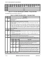
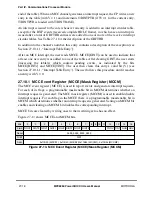
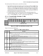
The data length and buffer pointer are described below:
¥
Data length. The data length is the number of bytes the MCC should transmit from
this BDÕs data buffer. It is never modiÞed by the CP. The value of this Þeld should
be greater than zero.
¥
Tx buffer pointer. The transmit buffer pointer, which contains the address of the
associated data buffer, may be even or odd. The buffer may reside in either internal
or external memory. This value is never modiÞed by the CP.
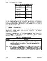
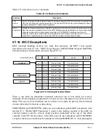
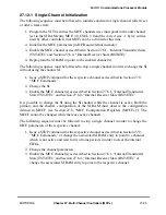
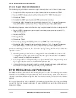
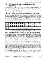
27.12 MCC Initialization and Start/Stop Sequence
The MCC must be initialized and started/stopped in relation with the corresponding TDMs.
The following two sections present the initialization and start/stop sequences which must
be followed for single and super channels.
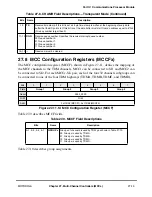
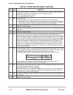
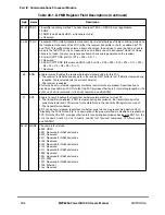
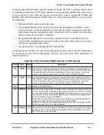
5
F
Tx CRC. Valid only when L = 1. Otherwise it must be ignored.
0 Transmit the closing ßag after the last data byte. This setting can be used for testing purposes to
send an erroneous CRC after the data.
1 Transmit the CRC sequence after the last data byte.
6
CM
Continuous mode
0 Normal operation.
1 The CP does not clear the ready bit after this BD is closed, allowing the associated data buffer to be
retransmitted automatically when the CP next accesses this BD. However, the R bit is cleared if an
error occurs during transmission, regardless of the CM bit setting.
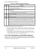
7
Ñ
Reserved, should be cleared.
8
UB
User bit. UB is a user-deÞned bit that the CPM never sets nor clears. The user determines how this bit
is used.
9Ð11
Ñ
Reserved, should be cleared.
12Ð15
PAD
Pad characters. These four bits indicate the number of PAD characters (0x7E or 0xFF depending on the
IDLM mode selected in the CHAMR register) that the transmitter sends after the closing ßag. The
transmitter issues a TXB interrupt only after sending the programmed number of pads to the Tx FIFO
buffer. The user can use the PAD value to guarantee that the TXB interrupt occurs after the closing ßag
has been sent out on the TXD line. PAD = 0, means that the TXB interrupt is issued immediately after
the closing ßag is sent to the Tx FIFO buffer. The number of PAD characters depends on the FIFO size
assigned to the channel in the MCC hardware. If the channel is not part of a super channel then the
MCC hardware assigns to this channel a Þfo of 4 bytes. So in this case a pad of 4 bytes ensure that the
TXB interrupt is not given before the closing ßag has been transmitted over the TXD line. For a super
channel, FIFO length equals the number of channels included in the super channel multiplied by four.
Table 27-16. TxBD Field Descriptions (Continued)
Bits
Name
Description
Summary of Contents for MPC8260 PowerQUICC II
Page 1: ...MPC8260UM D 4 1999 Rev 0 MPC8260 PowerQUICC II UserÕs Manual ª ª ...
Page 66: ...lxvi MPC8260 PowerQUICC II UserÕs Manual MOTOROLA ...
Page 88: ...1 18 MPC8260 PowerQUICC II UserÕs Manual MOTOROLA Part I Overview ...
Page 120: ...2 32 MPC8260 PowerQUICC II UserÕs Manual MOTOROLA Part I Overview ...
Page 138: ...Part II iv MPC8260 PowerQUICC II UserÕs Manual MOTOROLA Part II Configuration and Reset ...
Page 184: ...4 46 MPC8260 PowerQUICC II UserÕs Manual MOTOROLA Part II ConÞguration and Reset ...
Page 202: ...Part III vi MPC8260 PowerQUICC II UserÕs Manual MOTOROLA Part III The Hardware Interface ...
Page 266: ...8 34 MPC8260 PowerQUICC II UserÕs Manual MOTOROLA Part III The Hardware Interface ...
Page 382: ...10 106 MPC8260 PowerQUICC II UserÕs Manual MOTOROLA Part III The Hardware Interface ...
Page 392: ...11 10 MPC8260 PowerQUICC II UserÕs Manual MOTOROLA Part III The Hardware Interface ...
Page 430: ...Part IV viii MOTOROLA Part IV Communications Processor Module ...
Page 490: ...14 36 MPC8260 PowerQUICC II UserÕs Manual MOTOROLA Part IV Communications Processor Module ...
Page 524: ...17 10 MPC8260 PowerQUICC II UserÕs Manual MOTOROLA Part IV Communications Processor Module ...
Page 556: ...18 32 MPC8260 PowerQUICC II UserÕs Manual MOTOROLA Part IV Communications Processor Module ...
Page 584: ...19 28 MPC8260 PowerQUICC II UserÕs Manual MOTOROLA Part IV Communications Processor Module ...
Page 632: ...21 24 MPC8260 PowerQUICC II UserÕs Manual MOTOROLA Part IV Communications Processor Module ...
Page 652: ...22 20 MPC8260 PowerQUICC II UserÕs Manual MOTOROLA Part IV Communications Processor Module ...
Page 668: ...23 16 MPC8260 PowerQUICC II UserÕs Manual MOTOROLA Part IV Communications Processor Module ...
Page 758: ...27 28 MPC8260 PowerQUICC II UserÕs Manual MOTOROLA Part IV Communications Processor Module ...
Page 780: ...28 22 MPC8260 PowerQUICC II UserÕs Manual MOTOROLA Part IV Communications Processor Module ...
Page 874: ...29 94 MPC8260 PowerQUICC II UserÕs Manual MOTOROLA Part IV Communications Processor Module ...
Page 920: ...31 18 MPC8260 PowerQUICC II UserÕs Manual MOTOROLA Part IV Communications Processor Module ...
Page 980: ...A 4 MPC8260 PowerQUICC II UserÕs Manual MOTOROLA Appendixes ...
Page 1002: ...Index 22 MPC8260 PowerQUICC II UserÕs Manual MOTOROLA INDEX ...
Page 1006: ......

