24-6
MPC8260 PowerQUICC II UserÕs Manual
MOTOROLA
Part IV. Communications Processor Module
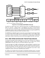
The Ethernet controller stores the Þrst 5 to 8 bytes of the transmit frame in dual-port RAM
so they need not be retrieved from system memory in case of a collision. This improves bus
usage and latency when the backoff timer output requires an immediate retransmission. If
a collision occurs during frame transmission, the controller returns to the Þrst buffer for a
retransmission. The only restriction is that the Þrst buffer must contain at least 9 bytes.
Note that if an Ethernet frame consists of multiple buffers, do not reuse the Þrst BD until
the CPM clears the R bit of the last BD.
When the end of the current BD is reached and TxBD[L] is set, the FCS bytes are appended
(if the TC bit is set in the TxBD), and TENA is negated. This notiÞes the EEST of the need
to generate the illegal Manchester encoding that marks the end of an Ethernet frame. After
CRC transmission, the Ethernet controller writes the frame status bits into the BD and
clears the R bit. When the end of the current BD is reached and the L bit is not set, only the
R bit is cleared.
In either mode, whether an interrupt is issued depends on how the I bit is set in the TxBD.
The Ethernet controller proceeds to the next TxBD. Transmission can be interrupted after
each frame, after each buffer, or after a speciÞc buffer is sent. The Ethernet controller can
pad characters to short frames. If TxBD[PAD] is set, the frame is padded up to the value of
the minimum frame length register (MINFLR).
To send expedited data before previously linked buffers or for error situations, the
GRACEFUL
STOP
TRANSMIT
command can be used to rearrange transmit queue before the
CPM sends all the frames; the Ethernet controller stops immediately if no transmission is
in progress or it will keep sending until the current frame either Þnishes or terminates with
a collision. When the Ethernet controller receives a
RESTART
TRANSMIT
command, it
resumes transmission. The Ethernet controller sends bytes least-signiÞcant bit Þrst.
24.5 SCC Ethernet Channel Frame Reception
The Ethernet receiver handles address recognition and performs CRC, short frame,
maximum DMA transfer, and maximum frame length checking with almost no core
intervention. When the core enables the Ethernet receiver, it enters hunt mode as soon as
RENA is asserted while CLSN is negated. In hunt mode, as data is shifted into the receive
shift register one bit at a time, the register contents are compared to the contents of the
SYN1 Þeld in the data synchronization register (DSR). This compare function becomes
valid a certain number of clocks after the start of the frame (depending on PSMR[NIB]). If
the two are not equal, the next bit is shifted in and the comparison is repeated. If a double-
zero or double-one fault is detected between bits 14 to 21 from the Þrst received preamble
bit, the frame is rejected. If a double-zero fault is detected after 21 bits from the Þrst
received preamble bit and before detection of the start frame delimiter (SFD), the frame is
also rejected. When the incoming pattern is not rejected and matches the DSR, the SFD has
been detected; hunt mode is terminated and character assembly begins.
When the receiver detects the Þrst bytes of the frame, the Ethernet controller performs
Summary of Contents for MPC8260 PowerQUICC II
Page 1: ...MPC8260UM D 4 1999 Rev 0 MPC8260 PowerQUICC II UserÕs Manual ª ª ...
Page 66: ...lxvi MPC8260 PowerQUICC II UserÕs Manual MOTOROLA ...
Page 88: ...1 18 MPC8260 PowerQUICC II UserÕs Manual MOTOROLA Part I Overview ...
Page 120: ...2 32 MPC8260 PowerQUICC II UserÕs Manual MOTOROLA Part I Overview ...
Page 138: ...Part II iv MPC8260 PowerQUICC II UserÕs Manual MOTOROLA Part II Configuration and Reset ...
Page 184: ...4 46 MPC8260 PowerQUICC II UserÕs Manual MOTOROLA Part II ConÞguration and Reset ...
Page 202: ...Part III vi MPC8260 PowerQUICC II UserÕs Manual MOTOROLA Part III The Hardware Interface ...
Page 266: ...8 34 MPC8260 PowerQUICC II UserÕs Manual MOTOROLA Part III The Hardware Interface ...
Page 382: ...10 106 MPC8260 PowerQUICC II UserÕs Manual MOTOROLA Part III The Hardware Interface ...
Page 392: ...11 10 MPC8260 PowerQUICC II UserÕs Manual MOTOROLA Part III The Hardware Interface ...
Page 430: ...Part IV viii MOTOROLA Part IV Communications Processor Module ...
Page 490: ...14 36 MPC8260 PowerQUICC II UserÕs Manual MOTOROLA Part IV Communications Processor Module ...
Page 524: ...17 10 MPC8260 PowerQUICC II UserÕs Manual MOTOROLA Part IV Communications Processor Module ...
Page 556: ...18 32 MPC8260 PowerQUICC II UserÕs Manual MOTOROLA Part IV Communications Processor Module ...
Page 584: ...19 28 MPC8260 PowerQUICC II UserÕs Manual MOTOROLA Part IV Communications Processor Module ...
Page 632: ...21 24 MPC8260 PowerQUICC II UserÕs Manual MOTOROLA Part IV Communications Processor Module ...
Page 652: ...22 20 MPC8260 PowerQUICC II UserÕs Manual MOTOROLA Part IV Communications Processor Module ...
Page 668: ...23 16 MPC8260 PowerQUICC II UserÕs Manual MOTOROLA Part IV Communications Processor Module ...
Page 758: ...27 28 MPC8260 PowerQUICC II UserÕs Manual MOTOROLA Part IV Communications Processor Module ...
Page 780: ...28 22 MPC8260 PowerQUICC II UserÕs Manual MOTOROLA Part IV Communications Processor Module ...
Page 874: ...29 94 MPC8260 PowerQUICC II UserÕs Manual MOTOROLA Part IV Communications Processor Module ...
Page 920: ...31 18 MPC8260 PowerQUICC II UserÕs Manual MOTOROLA Part IV Communications Processor Module ...
Page 980: ...A 4 MPC8260 PowerQUICC II UserÕs Manual MOTOROLA Appendixes ...
Page 1002: ...Index 22 MPC8260 PowerQUICC II UserÕs Manual MOTOROLA INDEX ...
Page 1006: ......

