15. USING A DIRECT DRIVE MOTOR
15 - 4
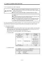
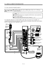
CAUTION
When using the regenerative resistor, switch power off with the alarm signal.
Otherwise, a transistor fault or the like may overheat the regenerative resistor,
causing a fire.
Do not modify the equipment.
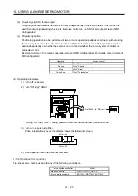
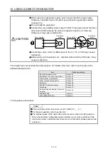
Connect the servo amplifier power output (U/V/W) to the power input of the direct
drive motor (U/V/W) directly. Do not let a magnetic contactor, etc. intervene.
Otherwise, it may cause a malfunction.
Servo amplifier
Servo amplifier
Direct drive
motor
Direct drive
motor
U
M
V
W
U
V
W
U
M
V
W
U
V
W
Connecting a servo motor for different axis to the U, V, W, or CN2 may cause a
malfunction.
Before wiring, switch operation, etc., eliminate static electricity. Otherwise, it may
cause a malfunction.
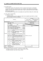
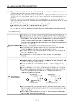
This chapter does not describe the following items. For details of the items, refer to each section of the
detailed description field.
Item Detailed
explanation
Input power supply circuit
Section 3.1
Explanation of power supply system
Section 3.3
Signal (device) explanations Section
3.5
Alarm occurrence timing chart
Section 3.7
Interfaces Section
3.8
SSCNET III cable connection
Section 3.9
Grounding Section
3.11
Switch setting and display of the servo
amplifier
Section 4.3
PARAMETERS Chapter
5
TROUBLESHOOTING Chapter
8
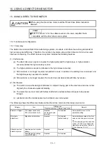
15.3 Operation and functions
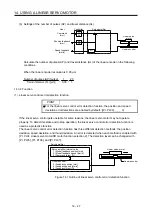
POINT
When using the direct drive motor, set [Pr. PA01] to "_ _ 6 _".
For the test operation, refer to section 4.4.
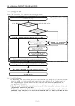
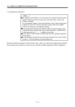
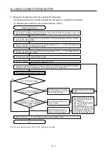
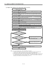
The Z-phase pulse of the direct drive motor must be turned on after power-on.
When the machine configuration does not allow one or more revolution of the
direct drive motor, install the direct drive motor so that the Z-phase pulse can be
turned on.
Summary of Contents for MR-J4-100B(-RJ)
Page 17: ...8 MEMO ...
Page 143: ...4 STARTUP 4 20 MEMO ...
Page 199: ...5 PARAMETERS 5 56 MEMO ...
Page 227: ...6 NORMAL GAIN ADJUSTMENT 6 28 MEMO ...
Page 281: ...8 TROUBLESHOOTING 8 16 MEMO ...
Page 303: ...9 DIMENSIONS 9 22 MEMO ...
Page 319: ...10 CHARACTERISTICS 10 16 MEMO ...
Page 429: ...11 OPTIONS AND PERIPHERAL EQUIPMENT 11 110 MEMO ...
Page 435: ...12 ABSOLUTE POSITION DETECTION SYSTEM 12 6 MEMO ...
Page 483: ...14 USING A LINEAR SERVO MOTOR 14 34 MEMO ...
Page 531: ...16 FULLY CLOSED LOOP SYSTEM 16 26 MEMO ...
Page 613: ...17 APPLICATION OF FUNCTIONS 17 82 MEMO ...
Page 654: ...APPENDIX App 41 ...

