


13. USING STO FUNCTION
13 - 9
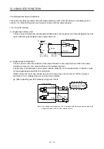
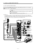
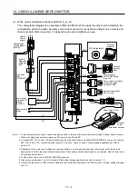
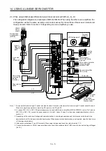
(2) Basic operation example
The switch status of STOA is input to SDI2A+ of MR-J3-D05, and then it will be input to STO1 and STO2
of the servo amplifier via SDO1A and SDO2A of MR-J3-D05.
The switch status of STOB is input to SDI2B+ of MR-J3-D05, and then it will be input to STO1 and STO2
of the servo amplifier via SDO1B and SDO2B of MR-J3-D05.
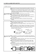
A-axis shutdown 1 and 2
B-axis shutdown 1 and 2
STO1, STO2
Stop
Operation
Energizing (close)
Shut-off (open)
EM2 input
STO shut-off
Normal (close)
Shut-off (open)
0 r/min
Servo motor drivable
Servo motor speed
Servo amplifier
Shut off delay
STO status
Summary of Contents for MR-J4-100B(-RJ)
Page 17: ...8 MEMO ...
Page 143: ...4 STARTUP 4 20 MEMO ...
Page 199: ...5 PARAMETERS 5 56 MEMO ...
Page 227: ...6 NORMAL GAIN ADJUSTMENT 6 28 MEMO ...
Page 281: ...8 TROUBLESHOOTING 8 16 MEMO ...
Page 303: ...9 DIMENSIONS 9 22 MEMO ...
Page 319: ...10 CHARACTERISTICS 10 16 MEMO ...
Page 429: ...11 OPTIONS AND PERIPHERAL EQUIPMENT 11 110 MEMO ...
Page 435: ...12 ABSOLUTE POSITION DETECTION SYSTEM 12 6 MEMO ...
Page 483: ...14 USING A LINEAR SERVO MOTOR 14 34 MEMO ...
Page 531: ...16 FULLY CLOSED LOOP SYSTEM 16 26 MEMO ...
Page 613: ...17 APPLICATION OF FUNCTIONS 17 82 MEMO ...
Page 654: ...APPENDIX App 41 ...