


APPENDIX
App. - 46
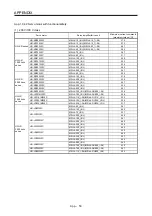
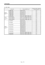
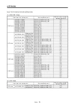
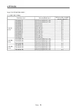
App. 10.2 Setting
POINT
When you use a linear servo motor, replace the following words in the left to the
words in the right.
(servo motor) speed
→
(linear servo motor) speed
CCW direction
→
Positive direction
CW direction
→
Negative direction
Torque
→
Thrust
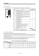
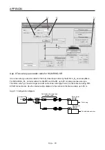
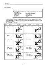
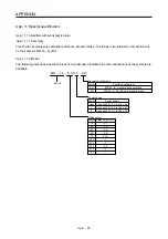
The servo amplifier is factory-set to output the servo motor speed to MO1 (Analog monitor 1) and the
torque to MO2 (Analog monitor 2). The setting can be changed as listed below by setting the [Pr. PC09]
and [Pr. PC10] value.
Refer to (3) for the detection point.
Setting
value
Output item
Description
Setting
value
Output item
Description
00
Servo motor speed/
Linear servo motor
speed
Maximum speed
CW direction
CCW direction
Maximum speed
0
8 [V]
-8 [V]
01
Torque/Thrust (Note 8)
Maximum torque
Power running in
CW direction
Power running in
CCW direction
Maximum torque
0
8 [V]
-8 [V]
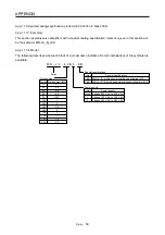
02
Servo motor speed/
Linear servo motor
speed
Maximum speed
CW direction
CCW direction
Maximum speed
0
8 [V]
03
Torque/Thrust (Note 8)
Maximum torque
Power running in
CW direction
Power running in
CCW direction
Maximum torque
0
8 [V]
04 Current
command
(Note 8)
Maximum current command
(Maximum torque command)
CW direction
CCW direction
Maximum current command
(Maximum torque command)
0
8 [V]
-8 [V]
05 Speed
command
Maximum speed
CW direction
CCW direction
Maximum speed
0
8 [V]
-8 [V]
06
Servo motor-side droop
pulses
(Note 1, 3, 5, 6)
(±10 V/100 pulses)
100 [pulse]
CW direction
CCW direction
100 [pulse]
0
10 [V]
-10 [V]
07
Servo motor-side droop
pulses
(Note 1, 3, 5, 6)
(±10 V/1000 pulses)
1000 [pulse]
CW direction
CCW direction
1000 [pulse]
0
10 [V]
-10 [V]
08
Servo motor-side droop
pulses
(Note 1, 3, 5, 6)
(±10 V/10000 pulses)
10000 [pulse]
CW direction
CCW direction
10000 [pulse]
0
10 [V]
-10 [V]
09
Servo motor-side droop
pulses
(Note 1, 3, 5, 6)
(±10 V/100000 pulses)
100000 [pulse]
CW direction
CCW direction
100000 [pulse]
0
10 [V]
-10 [V]
Summary of Contents for MR-J4-100B(-RJ)
Page 17: ...8 MEMO ...
Page 143: ...4 STARTUP 4 20 MEMO ...
Page 199: ...5 PARAMETERS 5 56 MEMO ...
Page 227: ...6 NORMAL GAIN ADJUSTMENT 6 28 MEMO ...
Page 281: ...8 TROUBLESHOOTING 8 16 MEMO ...
Page 303: ...9 DIMENSIONS 9 22 MEMO ...
Page 319: ...10 CHARACTERISTICS 10 16 MEMO ...
Page 429: ...11 OPTIONS AND PERIPHERAL EQUIPMENT 11 110 MEMO ...
Page 435: ...12 ABSOLUTE POSITION DETECTION SYSTEM 12 6 MEMO ...
Page 483: ...14 USING A LINEAR SERVO MOTOR 14 34 MEMO ...
Page 531: ...16 FULLY CLOSED LOOP SYSTEM 16 26 MEMO ...
Page 613: ...17 APPLICATION OF FUNCTIONS 17 82 MEMO ...
Page 654: ...APPENDIX App 41 ...