


APPENDIX
App. - 33
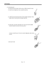
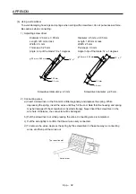
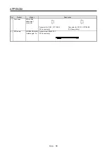
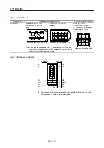
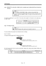
(3) Connector insertion
Insert the connector all the way straight until you hear or feel clicking. When removing the connector,
depress the lock part completely before pulling out. If the connector is pulled out without depressing the
lock part completely, the housing, contact and/or wires may be damaged.
(4) Compatible wire
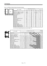
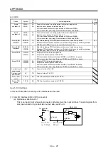
Compatible wire size is listed below.
Wire size
mm
2
AWG
0.22 24
0.34 22
0.50 20
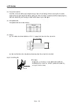
(5) Others
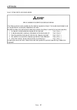
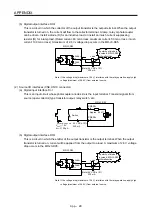
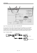
(a) Fix a cable tie at least distance of "A" × 1.5 away from the end of the connector.
A × 1.5 or more
A
(b) Be sure that wires are not pulled excessively when the connector is inserted.
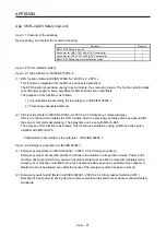
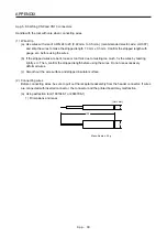
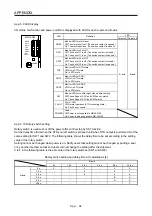
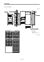
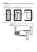
App. 5.8.4 Wiring FG
Bottom face
Lead wire
Wire range
Single
wire:
φ
0.4 mm to 1.2 mm (AWG 26 to AWG 16)
Stranded wire: 0.2 mm
2
to 1.25 mm
2
(AWG 24 to AWG 16),
wire
φ
0.18 mm or more
Summary of Contents for MR-J4-100B(-RJ)
Page 17: ...8 MEMO ...
Page 143: ...4 STARTUP 4 20 MEMO ...
Page 199: ...5 PARAMETERS 5 56 MEMO ...
Page 227: ...6 NORMAL GAIN ADJUSTMENT 6 28 MEMO ...
Page 281: ...8 TROUBLESHOOTING 8 16 MEMO ...
Page 303: ...9 DIMENSIONS 9 22 MEMO ...
Page 319: ...10 CHARACTERISTICS 10 16 MEMO ...
Page 429: ...11 OPTIONS AND PERIPHERAL EQUIPMENT 11 110 MEMO ...
Page 435: ...12 ABSOLUTE POSITION DETECTION SYSTEM 12 6 MEMO ...
Page 483: ...14 USING A LINEAR SERVO MOTOR 14 34 MEMO ...
Page 531: ...16 FULLY CLOSED LOOP SYSTEM 16 26 MEMO ...
Page 613: ...17 APPLICATION OF FUNCTIONS 17 82 MEMO ...
Page 654: ...APPENDIX App 41 ...