


3. SIGNALS AND WIRING
3 - 38
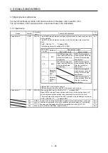
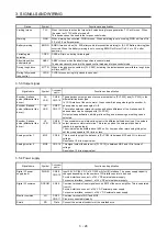
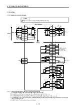
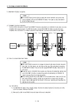
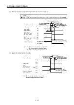
3.8.3 Source I/O interfaces
In this servo amplifier, source type I/O interfaces can be used.
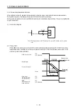
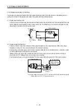
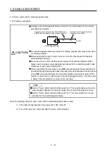
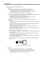
(1) Digital input interface DI-1
This is an input circuit whose photocoupler anode side is the input terminal. Transmit signals from
source (open-collector) type transistor output, relay switch, etc.
V
CES
1.0 V
I
CEO
100 µA
Approximately
6.2 k
Ω
DICOM
For transistor
Approximately
5 mA
TR
24 V DC ± 10%
300 mA
Switch
EM2,
etc.
Servo amplifier
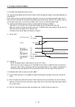
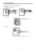
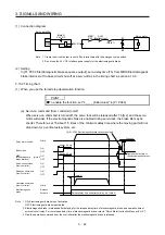
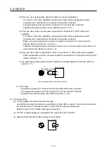
(2) Digital output interface DO-1
This is a circuit in which the emitter of the output transistor is the output terminal. When the output
transistor is turned on, current will be applied from the output to a load.
A maximum of 2.6 V voltage drop occurs in the servo amplifier.
(Note) 24 V DC ± 10%
300 mA
If polarity of diode is
reversed, servo amplifier
will malfunction.
Servo amplifier
ALM,
etc.
Load
DOCOM
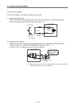
Note. If the voltage drop (maximum of 2.6 V) interferes with the relay operation, apply high
voltage (maximum of 26.4 V) from external source.
Summary of Contents for MR-J4-100B(-RJ)
Page 17: ...8 MEMO ...
Page 143: ...4 STARTUP 4 20 MEMO ...
Page 199: ...5 PARAMETERS 5 56 MEMO ...
Page 227: ...6 NORMAL GAIN ADJUSTMENT 6 28 MEMO ...
Page 281: ...8 TROUBLESHOOTING 8 16 MEMO ...
Page 303: ...9 DIMENSIONS 9 22 MEMO ...
Page 319: ...10 CHARACTERISTICS 10 16 MEMO ...
Page 429: ...11 OPTIONS AND PERIPHERAL EQUIPMENT 11 110 MEMO ...
Page 435: ...12 ABSOLUTE POSITION DETECTION SYSTEM 12 6 MEMO ...
Page 483: ...14 USING A LINEAR SERVO MOTOR 14 34 MEMO ...
Page 531: ...16 FULLY CLOSED LOOP SYSTEM 16 26 MEMO ...
Page 613: ...17 APPLICATION OF FUNCTIONS 17 82 MEMO ...
Page 654: ...APPENDIX App 41 ...


