

15. USING A DIRECT DRIVE MOTOR
15 - 22
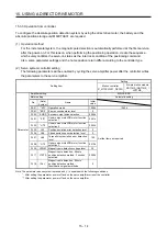
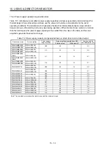
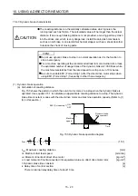
(2) Permissible load to motor inertia ratio when the dynamic brake is used
Use the dynamic brake under the load to motor inertia ratio indicated in the following table. If the load
inertia moment is higher than this value, the dynamic brake may burn. If the load to motor inertia ratio
exceeds the indicated value, contact your local sales office.
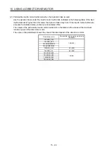
The values of the permissible load to motor inertia ratio in the table are the values at the maximum
rotation speed of the direct drive motor.
The value in the parenthesis shows the value at the rated speed of the direct drive motor.
Direct drive motor
Permissible load to motor inertia ratio
[multiplier]
TM-RFM_C20
100 (300)
TM-RFM_E20
TM-RG2M002C30
TM-RU2M002C30
TM-RFM_G20 50
(300)
TM-RFM_J10 50
(200)
TM-RG2M_E30
20 (80)
TM-RG2M_G30
TM-RU2M_E30
TM-RU2M_G30
Summary of Contents for MR-J4-100B(-RJ)
Page 17: ...8 MEMO ...
Page 143: ...4 STARTUP 4 20 MEMO ...
Page 199: ...5 PARAMETERS 5 56 MEMO ...
Page 227: ...6 NORMAL GAIN ADJUSTMENT 6 28 MEMO ...
Page 281: ...8 TROUBLESHOOTING 8 16 MEMO ...
Page 303: ...9 DIMENSIONS 9 22 MEMO ...
Page 319: ...10 CHARACTERISTICS 10 16 MEMO ...
Page 429: ...11 OPTIONS AND PERIPHERAL EQUIPMENT 11 110 MEMO ...
Page 435: ...12 ABSOLUTE POSITION DETECTION SYSTEM 12 6 MEMO ...
Page 483: ...14 USING A LINEAR SERVO MOTOR 14 34 MEMO ...
Page 531: ...16 FULLY CLOSED LOOP SYSTEM 16 26 MEMO ...
Page 613: ...17 APPLICATION OF FUNCTIONS 17 82 MEMO ...
Page 654: ...APPENDIX App 41 ...


