11. OPTIONS AND PERIPHERAL EQUIPMENT
11 - 32
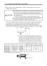
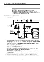
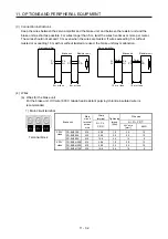
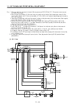
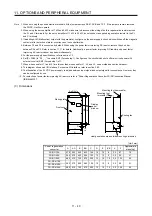
(3) Connection instructions
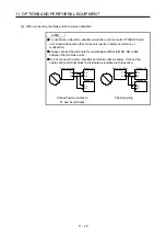
Keep the wires between the servo amplifier and the brake unit, and between the resistor unit and the
brake unit as short as possible. For wires longer than 5 m, twist the wires five times or more per meter.
The wires should not exceed 10 m even when the wires are twisted. If wires exceeding 5 m without
twisted or exceeding 10 m with or without twisted are used, the brake unit may malfunction.
Servo amplifier
Brake unit
5 m or less
5 m or less
Servo amplifier
Brake unit
10 m or less
10 m or less
P+
N-
P/+
N/-
P
PR
P
PR
P/+
N/-
P
PR
P
PR
Twist
Twist
Resistor unit
Resistor unit
P+
N-
(4) Wires
(a) Wires for the brake unit
For the brake unit, HIV wire (600 V Grade heat-resistant polyvinyl chloride insulated wire) is
recommended.
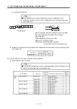
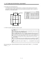
1) Main circuit terminal
N/-
P/+
PR
Terminal block
Brake unit
Main
circuit
terminal
screw
size
Crimp
terminal
Tightening
torque
[N•m]
Wire size
N/-, P/+,
PR,
N/-, P/+, PR,
HIV wire
[mm
2
]
AWG
200 V
class
FR-BU2-15K M4
5.5-4
1.5
3.5
12
FR-BU2-30K M5
5.5-5
2.5
5.5
10
FR-BU2-55K
M6 14-6 4.4 14
6
400 V
class
FR-BU2-H30K M4
5.5-4
1.5
3.5
12
FR-BU2-H55K M5
5.5-5
2.5
5.5
10
FR-BU2-H75K
M6 14-6 4.4 14
6
Summary of Contents for MR-J4-100B(-RJ)
Page 17: ...8 MEMO ...
Page 143: ...4 STARTUP 4 20 MEMO ...
Page 199: ...5 PARAMETERS 5 56 MEMO ...
Page 227: ...6 NORMAL GAIN ADJUSTMENT 6 28 MEMO ...
Page 281: ...8 TROUBLESHOOTING 8 16 MEMO ...
Page 303: ...9 DIMENSIONS 9 22 MEMO ...
Page 319: ...10 CHARACTERISTICS 10 16 MEMO ...
Page 429: ...11 OPTIONS AND PERIPHERAL EQUIPMENT 11 110 MEMO ...
Page 435: ...12 ABSOLUTE POSITION DETECTION SYSTEM 12 6 MEMO ...
Page 483: ...14 USING A LINEAR SERVO MOTOR 14 34 MEMO ...
Page 531: ...16 FULLY CLOSED LOOP SYSTEM 16 26 MEMO ...
Page 613: ...17 APPLICATION OF FUNCTIONS 17 82 MEMO ...
Page 654: ...APPENDIX App 41 ...

