11. OPTIONS AND PERIPHERAL EQUIPMENT
11 - 34
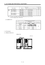
Servo amplifier
Brake unit
Number of
connected
units
Crimp terminal (Manufacturer)
(Note 1)
Applicable
tool
400 V
class
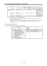
MR-J4-500B4(-RJ) FR-BU2-H30K
1
FVD5.5-S4
(JST)
a
MR-J4-700B4(-RJ) FR-BU2-H30K
1
FVD5.5-S4
(JST)
a
MR-J4-11KB4(-RJ) FR-BU2-H30K 1
FVD5.5-6
(JST)
a
FR-BU2-H55K 1
FVD5.5-6
(JST)
a
MR-J4-15KB4(-RJ) FR-BU2-H55K 1
FVD5.5-6
(JST)
a
MR-J4-22KB4(-RJ) FR-BU2-H55K 1
FVD5.5-8
(JST)
a
FR-BU2-H75K 1
FVD14-8
(JST)
d
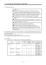
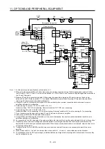
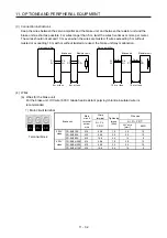
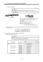
Note 1. Symbols in the applicable tool field indicate applicable tools in (4) (b) in this section.
2. Coat the crimping part with an insulation tube.
(b) Applicable tool
Symbol
Servo amplifier-side crimp terminals
Crimp terminal
Applicable tool
Manufacturer
Body Head Dice
a
FDV5.5-S4
FDV5.5-6
YNT-1210S
JST
b 8-4NS
YHT-8S
c FVD8-6
YF-1
E-4
YNE-38 DH-111
DH-121
d
FVD14-6
FVD14-8
YF-1
E-4
YNE-38 DH-112
DH-122
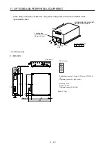
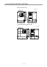
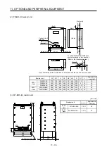
11.3.4 Dimensions
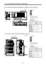
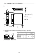
(1) FR-BU2-(H) brake unit
FR-BU2-15K
[Unit: mm]
Rating
plate
φ
5 hole
(Screw size: M4)
68
6
56
6
5
5
118
5
128
18.5
52
62
4
132.5
Summary of Contents for MR-J4-100B(-RJ)
Page 17: ...8 MEMO ...
Page 143: ...4 STARTUP 4 20 MEMO ...
Page 199: ...5 PARAMETERS 5 56 MEMO ...
Page 227: ...6 NORMAL GAIN ADJUSTMENT 6 28 MEMO ...
Page 281: ...8 TROUBLESHOOTING 8 16 MEMO ...
Page 303: ...9 DIMENSIONS 9 22 MEMO ...
Page 319: ...10 CHARACTERISTICS 10 16 MEMO ...
Page 429: ...11 OPTIONS AND PERIPHERAL EQUIPMENT 11 110 MEMO ...
Page 435: ...12 ABSOLUTE POSITION DETECTION SYSTEM 12 6 MEMO ...
Page 483: ...14 USING A LINEAR SERVO MOTOR 14 34 MEMO ...
Page 531: ...16 FULLY CLOSED LOOP SYSTEM 16 26 MEMO ...
Page 613: ...17 APPLICATION OF FUNCTIONS 17 82 MEMO ...
Page 654: ...APPENDIX App 41 ...

