


3. SIGNALS AND WIRING
3 - 10
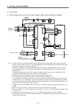
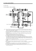
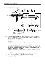
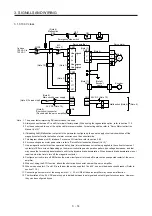
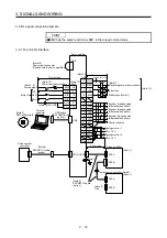
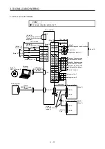
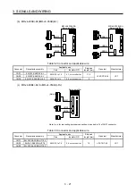
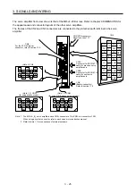
3.1.2 400 V class
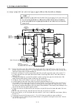
(1) MR-J4-60B4(-RJ) to MR-J4-350B4(-RJ)
(Note 7)
MC
ALM
DOCOM
CN3
(Note 5)
(Note 4)
Malfunction
RA1
L1
L2
L3
P3
P4
P+
L11
L21
N-
D
C
U
V
W
(Note 1)
(Note 10)
(Note 2)
CNP1
CNP3
CNP2
U
V
W
M
Motor
CN2
(Note 6)
(Note 11)
(Note 11)
(Note 4)
Malfunction
RA1
OFF
MC
ON
MC
SK
CN3
(Note 5) Forced stop 2
EM2
DICOM
CN8
(Note 9)
Short-circuit connector
(Packed with the servo amplifier)
(Note 8)
Main circuit power supply
MCCB
24 V DC (Note 13)
24 V DC (Note 13)
3-phase
380 V AC to
480 V AC
(Note 12)
Step-down
transformer
Emergency stop switch
Servo amplifier
Servo motor
Encoder
(Note 3)
Encoder cable
Note 1. Between P3 and P4 is connected by default. When using the power factor improving DC reactor, remove the short bar
between P3 and P4. Refer to section 11.11 for details. Additionally, a power factor improving DC reactor and power factor
improving AC reactor cannot be used simultaneously.
2.
Always connect between P+ and D terminals (factory-wired). When using the regenerative option, refer to section 11.2.
3. For the encoder cable, use of the option cable is recommended. For selecting cables, refer to "Servo Motor Instruction
Manual (Vol. 3)".
4. If disabling ALM (Malfunction) output with the parameter, configure up the power supply circuit which switches off the
magnetic contactor after detection of alarm occurrence on the controller side.
5. This diagram shows sink I/O interface. For source I/O interface, refer to section 3.8.3.
6. For connecting servo motor power wires, refer to "Servo Motor Instruction Manual (Vol. 3)".
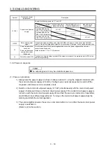
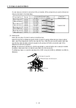
7. Use a magnetic contactor with an operation delay time (interval between current being applied to the coil until closure of
contacts) of 80 ms or less. Depending on the main circuit voltage and operation pattern, bus voltage decreases, and that
may cause the forced stop deceleration to shift to the dynamic brake deceleration. When dynamic brake deceleration is not
required, slow the time to turn off the magnetic contactor.
8. Configure a circuit to turn off EM2 when the main circuit power is turned off to prevent an unexpected restart of the servo
amplifier.
9. When not using the STO function, attach the short-circuit connector came with a servo amplifier.
10. When wires used for L11 and L21 are thinner than wires used for L1, L2, and L3, use a molded-case circuit breaker. (Refer
to section 11.10.)
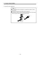
11. Connecting a servo motor for different axis to U, V, W, or CN2 of the servo amplifier may cause a malfunction.
12. Stepdown transformer is required when the coil voltage of the magnetic contactor is 200 V class.
13. The illustration of the 24 V DC power supply is divided between input signal and output signal for convenience. However,
they can be configured by one.
Summary of Contents for MR-J4-100B(-RJ)
Page 17: ...8 MEMO ...
Page 143: ...4 STARTUP 4 20 MEMO ...
Page 199: ...5 PARAMETERS 5 56 MEMO ...
Page 227: ...6 NORMAL GAIN ADJUSTMENT 6 28 MEMO ...
Page 281: ...8 TROUBLESHOOTING 8 16 MEMO ...
Page 303: ...9 DIMENSIONS 9 22 MEMO ...
Page 319: ...10 CHARACTERISTICS 10 16 MEMO ...
Page 429: ...11 OPTIONS AND PERIPHERAL EQUIPMENT 11 110 MEMO ...
Page 435: ...12 ABSOLUTE POSITION DETECTION SYSTEM 12 6 MEMO ...
Page 483: ...14 USING A LINEAR SERVO MOTOR 14 34 MEMO ...
Page 531: ...16 FULLY CLOSED LOOP SYSTEM 16 26 MEMO ...
Page 613: ...17 APPLICATION OF FUNCTIONS 17 82 MEMO ...
Page 654: ...APPENDIX App 41 ...