


1. FUNCTIONS AND CONFIGURATION
1 - 25
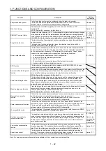
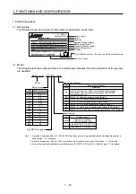
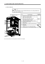
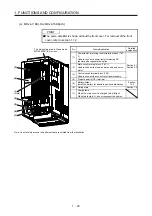
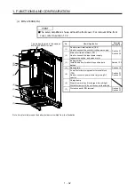
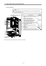
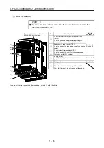
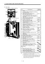
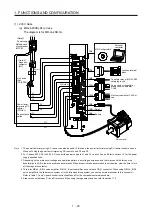
(b) MR-J4-350B(-RJ)
The broken line area is the same as
MR-J4-200B(-RJ) or less.
(1)
(3)
(2)
Side
(4)
(5)
(7)
(6)
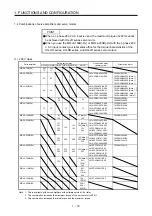
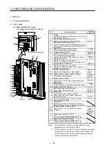
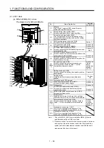
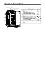
No. Name/Application
Detailed
explanation
(1)
Main circuit power connector (CNP1)
Connect the input power supply.
Section 3.1
Section 3.3
(2) Rating plate
Section 1.6
(3)
Servo motor power connector (CNP3)
Connect the servo motor.
Section 3.1
Section 3.3
(4)
Control circuit power connector (CNP2)
Connect the control circuit power supply and
regenerative option.
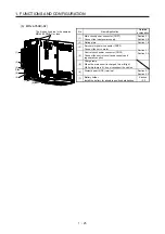
(5)
Charge lamp
When the main circuit is charged, this will light.
While this lamp is lit, do not reconnect the cables.
(6)
Protective earth (PE) terminal
Section 3.1
Section 3.3
(7)
Battery holder
Install the battery for absolute position data backup.
Section
12.2
Summary of Contents for MR-J4-100B(-RJ)
Page 17: ...8 MEMO ...
Page 143: ...4 STARTUP 4 20 MEMO ...
Page 199: ...5 PARAMETERS 5 56 MEMO ...
Page 227: ...6 NORMAL GAIN ADJUSTMENT 6 28 MEMO ...
Page 281: ...8 TROUBLESHOOTING 8 16 MEMO ...
Page 303: ...9 DIMENSIONS 9 22 MEMO ...
Page 319: ...10 CHARACTERISTICS 10 16 MEMO ...
Page 429: ...11 OPTIONS AND PERIPHERAL EQUIPMENT 11 110 MEMO ...
Page 435: ...12 ABSOLUTE POSITION DETECTION SYSTEM 12 6 MEMO ...
Page 483: ...14 USING A LINEAR SERVO MOTOR 14 34 MEMO ...
Page 531: ...16 FULLY CLOSED LOOP SYSTEM 16 26 MEMO ...
Page 613: ...17 APPLICATION OF FUNCTIONS 17 82 MEMO ...
Page 654: ...APPENDIX App 41 ...