17. APPLICATION OF FUNCTIONS
17 - 41
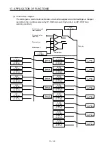
(5) Filter setting
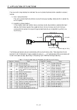
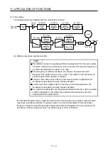
The following filters are available with the J3 extension function.
Command
pulse train
Command
filter
Low-pass
filter
setting
Encoder
Servo motor
PWM
M
Load
[Pr. PB18]
+
-
Machine
resonance
suppression
filter 1
[Pr. PB13]
[Pr. PB15]
Machine
resonance
suppression
filter 2
Machine
resonance
suppression
filter 3
Machine
resonance
suppression
filter 4
Machine
resonance
suppression
filter 5
Shaft
resonance
suppression
filter
Robust filter
[Pr. PB17]
Speed
control
[Pr. PX17]
[Pr. PX19]
[Pr. PX21]
[Pr. PX20]
[Pr. PX31]
(a) Machine resonance suppression filter
POINT
The machine resonance suppression filter is a delay factor for the servo system.
Therefore, vibration may increase if you set an incorrect resonance frequency or
set notch characteristics too deep or too wide.
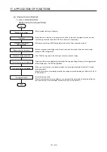
If the frequency of machine resonance is unknown, decrease the notch
frequency from higher to lower ones in order. The optimum notch frequency is
set at the point where vibration is minimal.
A deeper notch has a higher effect on machine resonance suppression but
increases a phase delay and may increase vibration.
A wider notch has a higher effect on machine resonance suppression but
increases a phase delay and may increase vibration.
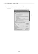
The machine characteristic can be grasped beforehand by the machine analyzer
on MR Configurator2. This allows the required notch frequency and notch
characteristics to be determined.
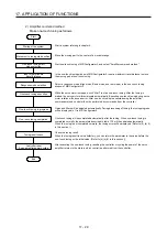
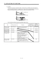
If a mechanical system has a unique resonance point, increasing the servo system response level
may cause resonance (vibration or unusual noise) in the mechanical system at that resonance
frequency. Using the machine resonance suppression filter and adaptive tuning can suppress the
resonance of the mechanical system. The setting range is 10 Hz to 4500 Hz.
Summary of Contents for MR-J4-100B(-RJ)
Page 17: ...8 MEMO ...
Page 143: ...4 STARTUP 4 20 MEMO ...
Page 199: ...5 PARAMETERS 5 56 MEMO ...
Page 227: ...6 NORMAL GAIN ADJUSTMENT 6 28 MEMO ...
Page 281: ...8 TROUBLESHOOTING 8 16 MEMO ...
Page 303: ...9 DIMENSIONS 9 22 MEMO ...
Page 319: ...10 CHARACTERISTICS 10 16 MEMO ...
Page 429: ...11 OPTIONS AND PERIPHERAL EQUIPMENT 11 110 MEMO ...
Page 435: ...12 ABSOLUTE POSITION DETECTION SYSTEM 12 6 MEMO ...
Page 483: ...14 USING A LINEAR SERVO MOTOR 14 34 MEMO ...
Page 531: ...16 FULLY CLOSED LOOP SYSTEM 16 26 MEMO ...
Page 613: ...17 APPLICATION OF FUNCTIONS 17 82 MEMO ...
Page 654: ...APPENDIX App 41 ...

