17. APPLICATION OF FUNCTIONS
17 - 71
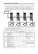
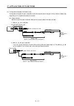
Eight master axes can be set at most per one system of SSCNET III/H. The maximum number of slave
axes to each master axis is not limited. However, the total number of the master and slave axes should
be the maximum number of the servo amplifiers at most. In addition, when an SSCNET III/H
communication shut-off occurs due to malfunction of a servo amplifier, the malfunctioning axis and later
axis cannot be communicated. Therefore, the first amplifier from the controller via SSCNET III/H cable
should be master axis.
Master axis
MR-J4-_B_(-RJ)
CN2
CN2
CN2
CN2
Slave axis 1
MR-J4-_B_(-RJ)
Slave axis 2
MR-J4-_B_(-RJ)
Slave axis 3
MR-J4-_B_(-RJ)
These are for the
same machine.
Controller
Position
command
[Driver communication]
Torque command
Speed limit command
[Driver communication]
[Driver communication]
Torque command
Speed limit command
Torque command
Speed limit command
(3) Parameter setting for the master-slave operation function
To use the master-slave operation function, the following parameter settings are necessary. For details
of the parameters, refer to section 5.2.1 and 5.2.4.
No. Name
Initial
value
Setting value
Setting
Master axis
Slave axis
PA04
Forced stop deceleration
function selection
2000
0 _ _ _
0 _ _ _
Used to disable the forced stop
deceleration function.
PA14
Rotation direction
selection/travel direction
selection
0
Refer to section 5.2.1.
Used to set a torque generation
direction.
PD15 (Note)
Driver communication setting
0000
0001
0010
Master and slave setting
PD16 (Note)
Driver communication setting -
Master - Transmit data
selection 1
0000 0038 0000
Communication data from master to
slave
Torque command
Speed limit value
PD17 (Note)
Driver communication setting -
Master - Transmit data
selection 2
0000 003A 0000
PD20 (Note)
Master axis No. selection 1 for
slave
0 0
Master axis
No.
Master axis No. of transmitting data
PD30
Master-slave operation -
Torque command coefficient on
slave
0 0
Refer to
section 5.2.4.
Ratio of torque command of slave
axis, ratio of speed limit value, and
setting of speed limit minimum value
PD31
Master-slave operation - Speed
limit coefficient on slave
0 0
PD32
Master-slave operation - Speed
limit adjusted value on slave
0 0
Note. Always set this with parameters of the controller.
Summary of Contents for MR-J4-100B(-RJ)
Page 17: ...8 MEMO ...
Page 143: ...4 STARTUP 4 20 MEMO ...
Page 199: ...5 PARAMETERS 5 56 MEMO ...
Page 227: ...6 NORMAL GAIN ADJUSTMENT 6 28 MEMO ...
Page 281: ...8 TROUBLESHOOTING 8 16 MEMO ...
Page 303: ...9 DIMENSIONS 9 22 MEMO ...
Page 319: ...10 CHARACTERISTICS 10 16 MEMO ...
Page 429: ...11 OPTIONS AND PERIPHERAL EQUIPMENT 11 110 MEMO ...
Page 435: ...12 ABSOLUTE POSITION DETECTION SYSTEM 12 6 MEMO ...
Page 483: ...14 USING A LINEAR SERVO MOTOR 14 34 MEMO ...
Page 531: ...16 FULLY CLOSED LOOP SYSTEM 16 26 MEMO ...
Page 613: ...17 APPLICATION OF FUNCTIONS 17 82 MEMO ...
Page 654: ...APPENDIX App 41 ...

