14. USING A LINEAR SERVO MOTOR
14 - 32
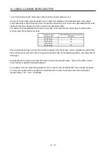
14.4.3 Dynamic brake characteristics
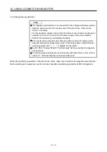
CAUTION
The coasting distance is a theoretically calculated value which ignores the
running load such as friction. The calculated value is considered to be longer than
the actual distance. However, if an enough braking distance is not provided, a
moving part may crash into the stroke end, which is very dangerous. Install the
anti-crash mechanism such as an air brake or an electric/mechanical stopper
such as a shock absorber to reduce the shock of moving parts. No linear servo
motor with an electromagnetic brake is available.
POINT
Do not use dynamic brake to stop in a normal operation as it is the function to
stop in emergency.
For a machine operating at the recommended load to motor mass ratio or less,
the estimated number of usage times of the dynamic brake is 1000 times while
the machine decelerates from the rated speed to a stop once in 10 minutes.
Be sure to enable EM1 (Forced stop 1) after the linear servo motor stops when
using EM1 (Forced stop 1) frequently in other than emergency.
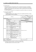
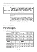
The approximate coasting distance from when the dynamic brake is activated until when the linear servo
motor stops can be calculated with the equation below.
Lmax = V
0
• (0.03 + M • (A + B • V
0
2
))
Lmax: Coasting distance of the machine [m]
V
0
: Speed when the brake is activated [m/s]
M: Full mass of the moving part [kg]
A: Coefficient (Refer to the following tables.)
B: Coefficient (Refer to the following tables.)
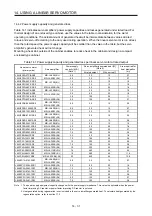
Linear servo motor
(primary side)
Coefficient A
Coefficient B
Linear servo motor
(primary side)
Coefficient A
Coefficient B
LM-H3P2A-07P-BSS0
7.15 × 10
-3
2.94 × 10
-3
LM-U2PAB-05M-0SS0
5.72 × 10
-2
1.72 × 10
-4
LM-H3P3A-12P-CSS0
2.81 × 10
-3
1.47 × 10
-3
LM-U2PAD-10M-0SS0
2.82 × 10
-2
8.60 × 10
-5
LM-H3P3B-24P-CSS0
7.69 × 10
-3
2.27 × 10
-4
LM-U2PAF-15M-0SS0
1.87 × 10
-2
5.93 × 10
-5
LM-H3P3C-36P-CSS0
7.22 × 10
-3
1.13 × 10
-4
LM-U2PBB-07M-1SS0
3.13 × 10
-2
1.04 × 10
-4
LM-H3P3D-48P-CSS0
1.02 × 10
-3
2.54 × 10
-4
LM-U2PBD-15M-1SS0
1.56 × 10
-2
5.18 × 10
-5
LM-H3P7A-24P-ASS0
7.69 × 10
-3
2.14 × 10
-4
LM-U2PBF-22M-1SS0
4.58 × 10
-2
1.33 × 10
-5
LM-H3P7B-48P-ASS0
9.14 × 10
-4
2.59 × 10
-4
LM-U2P2B-40M-2SS0
1.47 × 10
-3
1.27 × 10
-5
LM-H3P7C-72P-ASS0
7.19 × 10
-4
1.47 × 10
-4
LM-U2P2C-60M-2SS0
1.07 × 10
-3
7.66 × 10
-6
LM-H3P7D-96P-ASS0
6.18 × 10
-4
9.59 × 10
-5
LM-U2P2D-80M-2SS0
9.14 × 10
-4
5.38 × 10
-6
Linear servo motor
(primary side)
Coefficient A
Coefficient B
Linear servo motor
(primary side)
Coefficient A
Coefficient B
LM-FP2B-06M-1SS0
8.96 × 10
-4
1.19 × 10
-3
LM-K2P1A-01M-2SS1
5.36 × 10
-3
6.56 × 10
-3
LM-FP2D-12M-1SS0
5.55 × 10
-4
4.81 × 10
-4
LM-K2P1C-03M-2SS1
1.17 × 10
-3
3.75 × 10
-4
LM-FP2F-18M-1SS0
4.41 × 10
-4
2.69 × 10
-4
LM-K2P2A-02M-1SS1
2.49 × 10
-2
1.02 × 10
-3
LM-FP4B-12M-1SS0
5.02 × 10
-4
4.36 × 10
-4
LM-K2P2C-07M-1SS1
6.85 × 10
-4
2.80 × 10
-4
LM-FP4D-24M-1SS0
3.55 × 10
-4
1.54 × 10
-4
LM-K2P2E-12M-1SS1
5.53 × 10
-4
1.14 × 10
-4
LM-FP4F-36M-1SS0
1.79 × 10
-4
1.36 × 10
-4
LM-K2P3C-14M-1SS1
2.92 × 10
-4
1.16 × 10
-4
LM-FP4H-48M-1SS0
1.15 × 10
-4
1.19 × 10
-4
LM-K2P3E-24M-1SS1
2.53 × 10
-4
5.52 × 10
-5
LM-FP5H-60M-1SS0
1.95 × 10
-4
4.00 × 10
-5
Summary of Contents for MR-J4-100B(-RJ)
Page 17: ...8 MEMO ...
Page 143: ...4 STARTUP 4 20 MEMO ...
Page 199: ...5 PARAMETERS 5 56 MEMO ...
Page 227: ...6 NORMAL GAIN ADJUSTMENT 6 28 MEMO ...
Page 281: ...8 TROUBLESHOOTING 8 16 MEMO ...
Page 303: ...9 DIMENSIONS 9 22 MEMO ...
Page 319: ...10 CHARACTERISTICS 10 16 MEMO ...
Page 429: ...11 OPTIONS AND PERIPHERAL EQUIPMENT 11 110 MEMO ...
Page 435: ...12 ABSOLUTE POSITION DETECTION SYSTEM 12 6 MEMO ...
Page 483: ...14 USING A LINEAR SERVO MOTOR 14 34 MEMO ...
Page 531: ...16 FULLY CLOSED LOOP SYSTEM 16 26 MEMO ...
Page 613: ...17 APPLICATION OF FUNCTIONS 17 82 MEMO ...
Page 654: ...APPENDIX App 41 ...

