1. FUNCTIONS AND CONFIGURATION
1 - 12
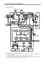
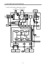
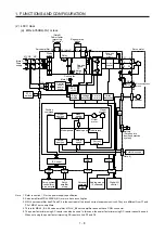
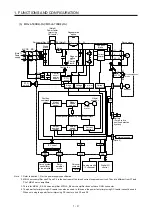
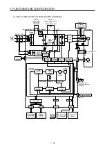
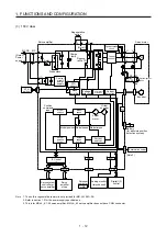
(3) 100 V class
Model position
Current
control
Actual
position
control
Actual
speed
control
Virtual
motor
Virtual
encoder
L11
L21
Encoder
N-
C
D
L2
L1
Dynamic brake
circuit
Current
detection
Overcurrent
protection
Voltage
detection
(Note 2)
Power
supply
MC
MCCB
Base
amplifier
STO
circuit
CN5
USB
USB
Personal
computer
Servo system
controller or
servo amplifier
Servo
amplifier
or cap
CN1A
CN1B
D/A
Analog monitor
(two channel)
Position
command
input
CN3
Servo amplifier
U
V
W
U
V
W
Diode stack
Relay
P+
+
+
B
RA
24 V DC
B1
B2
Battery
(for absolute position
detection system)
CN4
STO
switch
Model speed Model torque
M
CN2
CN8
Control
circuit
power
supply
Model
position
control
Model
speed
control
IF Control
Servo motor
Charge
lamp
Regene-
rative TR
Current
encoder
Digital I/O
control
Regenerative
option
U
Step-
down
circuit
External encoder
CN2L
(Note 3)
+
Electromagnetic
brake
(Note 1)
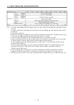
Note 1. The built-in regenerative resistor is not provided for MR-J4-10B1(-RJ).
2. Refer to section 1.3 for the power supply specifications.
3. This is for MR-J4-_B1-RJ servo amplifier. MR-J4-_B1 servo amplifier does not have CN2L connector.
Summary of Contents for MR-J4-100B(-RJ)
Page 17: ...8 MEMO ...
Page 143: ...4 STARTUP 4 20 MEMO ...
Page 199: ...5 PARAMETERS 5 56 MEMO ...
Page 227: ...6 NORMAL GAIN ADJUSTMENT 6 28 MEMO ...
Page 281: ...8 TROUBLESHOOTING 8 16 MEMO ...
Page 303: ...9 DIMENSIONS 9 22 MEMO ...
Page 319: ...10 CHARACTERISTICS 10 16 MEMO ...
Page 429: ...11 OPTIONS AND PERIPHERAL EQUIPMENT 11 110 MEMO ...
Page 435: ...12 ABSOLUTE POSITION DETECTION SYSTEM 12 6 MEMO ...
Page 483: ...14 USING A LINEAR SERVO MOTOR 14 34 MEMO ...
Page 531: ...16 FULLY CLOSED LOOP SYSTEM 16 26 MEMO ...
Page 613: ...17 APPLICATION OF FUNCTIONS 17 82 MEMO ...
Page 654: ...APPENDIX App 41 ...


