


14. USING A LINEAR SERVO MOTOR
14 - 29
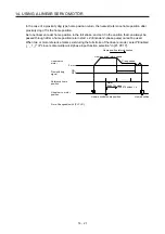
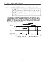
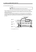
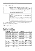
(2) Auto tuning function
POINT
The auto tuning mode 1 may not be performed properly if the following
conditions are not satisfied.
Time to reach 2000 mm/s is the acceleration/deceleration time constant of 5 s
or less.
The linear servo motor speed is 150 mm/s or higher.
The load to mass of the linear servo motor primary-side ratio is 100 times or
less.
The acceleration/deceleration thrust is 10% or less of the continuous thrust.
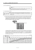
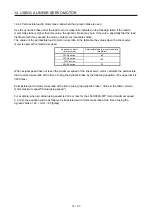
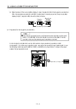
The auto tuning function during the linear servo motor operation is the same as that of the rotary servo
motor. However, the calculation method of the load to motor mass ratio (J ratio) differs. The load to
motor mass ratio (J ratio) on the linear servo motor is calculated by dividing the load mass by the mass
of the linear servo motor primary side.
Example) Mass of linear servo motor primary side
Load mass (excluding the mass of the linear servo motor primary side)
Mass ratio
= 2 kg
= 4 kg
= 4/2 = 2 times
For the parameters set by the auto tuning function, refer to chapter 6.
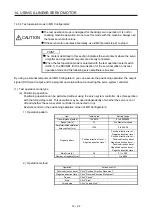
(3) Machine analyzer function
POINT
Make sure to perform the machine analyzer function after the magnetic pole
detection. If the magnetic pole detection is not performed, the machine analyze
function may not operate properly.
The stop position at the completion of the machine analyzer function can be any
position.
14.3.7 Absolute position detection system
When the linear servo motor is used with the absolute position detection system, an absolute position linear
encoder is required. The linear encoder backs up the absolute position data. Therefore, the encoder battery
need not be installed to the servo amplifier. Additionally, [AL. 25 Absolute position erased], [AL. 92 Battery
cable disconnection warning], [AL. 9F Battery warning], and [AL. E3 Absolute position counter warning] are
not provided for the linear servo motor.
Summary of Contents for MR-J4-100B(-RJ)
Page 17: ...8 MEMO ...
Page 143: ...4 STARTUP 4 20 MEMO ...
Page 199: ...5 PARAMETERS 5 56 MEMO ...
Page 227: ...6 NORMAL GAIN ADJUSTMENT 6 28 MEMO ...
Page 281: ...8 TROUBLESHOOTING 8 16 MEMO ...
Page 303: ...9 DIMENSIONS 9 22 MEMO ...
Page 319: ...10 CHARACTERISTICS 10 16 MEMO ...
Page 429: ...11 OPTIONS AND PERIPHERAL EQUIPMENT 11 110 MEMO ...
Page 435: ...12 ABSOLUTE POSITION DETECTION SYSTEM 12 6 MEMO ...
Page 483: ...14 USING A LINEAR SERVO MOTOR 14 34 MEMO ...
Page 531: ...16 FULLY CLOSED LOOP SYSTEM 16 26 MEMO ...
Page 613: ...17 APPLICATION OF FUNCTIONS 17 82 MEMO ...
Page 654: ...APPENDIX App 41 ...