11. OPTIONS AND PERIPHERAL EQUIPMENT
11 - 67
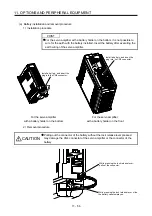
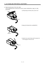
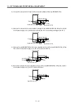
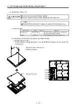
c) Assembly of the case
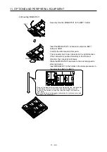
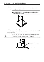
After all MR-BAT6V1 batteries are mounted, fit the cover and insert screws into the two holes
and tighten them. Tightening torque is 0.71 N•m.
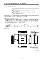
POINT
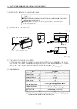
When assembling the case, be careful not to get the lead wires caught in the
fitting parts or the screwing parts.
Threads
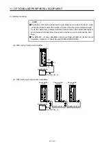
d) Precautions for removal of battery
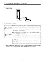
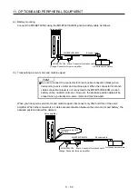
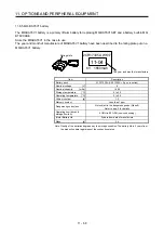
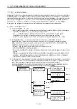
The connector attached to the MR-BAT6V1 battery has the lock release lever. When removing
the connector, pull out the connector while pressing the lock release lever.
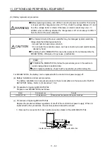
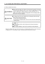
3) Battery cable removal
CAUTION
Pulling out the connector of the MR-BT6V1CBL and the MR-BT6V2CBL without
the lock release lever pressed may damage the CN4 connector of the servo
amplifier or the connector of the MR-BT6V1CBL or MR-BT6V2CBL.
While pressing the lock release lever,
pull out the connector.
Battery cable
Summary of Contents for MR-J4-100B(-RJ)
Page 17: ...8 MEMO ...
Page 143: ...4 STARTUP 4 20 MEMO ...
Page 199: ...5 PARAMETERS 5 56 MEMO ...
Page 227: ...6 NORMAL GAIN ADJUSTMENT 6 28 MEMO ...
Page 281: ...8 TROUBLESHOOTING 8 16 MEMO ...
Page 303: ...9 DIMENSIONS 9 22 MEMO ...
Page 319: ...10 CHARACTERISTICS 10 16 MEMO ...
Page 429: ...11 OPTIONS AND PERIPHERAL EQUIPMENT 11 110 MEMO ...
Page 435: ...12 ABSOLUTE POSITION DETECTION SYSTEM 12 6 MEMO ...
Page 483: ...14 USING A LINEAR SERVO MOTOR 14 34 MEMO ...
Page 531: ...16 FULLY CLOSED LOOP SYSTEM 16 26 MEMO ...
Page 613: ...17 APPLICATION OF FUNCTIONS 17 82 MEMO ...
Page 654: ...APPENDIX App 41 ...

