


17. APPLICATION OF FUNCTIONS
17 - 53
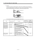
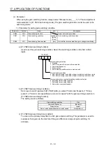
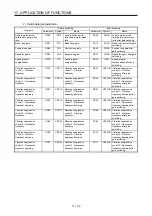
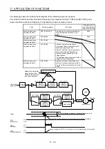
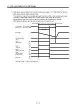
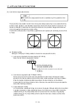
a) [Pr. PB06] to [Pr. PB10]
These parameters are the same as in ordinary manual adjustment. Gain switching allows the
values of load to motor inertia ratio/load to motor mass ratio, model loop gain, position loop
gain, speed loop gain, and speed integral compensation to be switched.
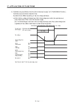
b) [Pr. PB19] to [Pr. PB22]/[Pr. PX04] to [Pr. PX07]
These parameters are the same as in ordinary manual adjustment. You can switch the
vibration frequency, resonance frequency, vibration frequency damping, and resonance
frequency damping by switching gain during motor stop.
c) [Pr. PB29 Load to motor inertia ratio/load to motor mass ratio after gain switching]
Set the load to motor inertia ratio or load to motor mass ratio after gain switching. If the load to
motor inertia ratio does not change, set it to the same value as [Pr. PB06 Load to motor inertia
ratio/load to motor mass ratio].
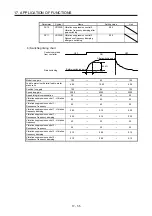
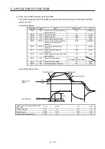
d) [Pr. PB30 Position loop gain after gain switching], [Pr. PB31 Speed loop gain after gain
switching], and [Pr. PB32 Speed integral compensation after gain switching]
Set the values of after switching position loop gain, speed loop gain and speed integral
compensation.
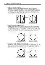
e) Vibration suppression control after gain switching ([Pr. PB33] to [Pr. PB36]/[Pr. PX08] to [Pr.
PX11]) , and [Pr. PX12 Model loop gain after gain switching]
The gain switching vibration suppression control and gain switching model loop gain are used
only with control command from the controller.
You can switch the vibration frequency, resonance frequency, vibration frequency damping,
resonance frequency damping, and model loop gain of the vibration suppression control 1 and
vibration suppression control 2.
Summary of Contents for MR-J4-100B(-RJ)
Page 17: ...8 MEMO ...
Page 143: ...4 STARTUP 4 20 MEMO ...
Page 199: ...5 PARAMETERS 5 56 MEMO ...
Page 227: ...6 NORMAL GAIN ADJUSTMENT 6 28 MEMO ...
Page 281: ...8 TROUBLESHOOTING 8 16 MEMO ...
Page 303: ...9 DIMENSIONS 9 22 MEMO ...
Page 319: ...10 CHARACTERISTICS 10 16 MEMO ...
Page 429: ...11 OPTIONS AND PERIPHERAL EQUIPMENT 11 110 MEMO ...
Page 435: ...12 ABSOLUTE POSITION DETECTION SYSTEM 12 6 MEMO ...
Page 483: ...14 USING A LINEAR SERVO MOTOR 14 34 MEMO ...
Page 531: ...16 FULLY CLOSED LOOP SYSTEM 16 26 MEMO ...
Page 613: ...17 APPLICATION OF FUNCTIONS 17 82 MEMO ...
Page 654: ...APPENDIX App 41 ...