2. INSTALLATION
2 - 3
(b) Installation of two or more servo amplifiers
POINT
Close mounting is possible depending on the capacity of the servo amplifier.
Refer to section 1.3 for availability of close mounting.
When closely mounting multiple servo amplifiers, the servo amplifier on the right
must have a larger depth than that on the left. Otherwise, the CNP1, CNP2, and
CNP3 connectors cannot be removed.
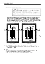
Leave a large clearance between the top of the servo amplifier and the cabinet walls, and install a
cooling fan to prevent the internal temperature of the cabinet from exceeding the environment.
When mounting the servo amplifiers closely, leave a clearance of 1 mm between the adjacent servo
amplifiers in consideration of mounting tolerances. In this case, keep the ambient temperature within
0
˚
C to 45
˚
C or use the servo amplifier with 75% or less of the effective load ratio.
100 mm or more
10 mm or more
(Note 2)
30 mm
or more
30 mm
or more
40 mm or more
(Note 1)
Cabinet
Top
Bottom
100 mm or more
1 mm
30 mm
or more
40 mm or more
Cabinet
1 mm
Leaving clearance
Mounting closely
Note 1. For 11 kW to 22 kW servo amplifiers, the clearance between the bottom and ground will be 120 mm or more.
2. When mounting MR-J4-500B(-RJ), maintain a minimum clearance of 25 mm between the MR-J4-500B(-RJ) and a servo
amplifier mounted on the left side.
(2) Others
When using heat generating equipment such as the regenerative option, install them with full
consideration of heat generation so that the servo amplifier is not affected.
Install the servo amplifier on a perpendicular wall in the correct vertical direction.
Summary of Contents for MR-J4-100B(-RJ)
Page 17: ...8 MEMO ...
Page 143: ...4 STARTUP 4 20 MEMO ...
Page 199: ...5 PARAMETERS 5 56 MEMO ...
Page 227: ...6 NORMAL GAIN ADJUSTMENT 6 28 MEMO ...
Page 281: ...8 TROUBLESHOOTING 8 16 MEMO ...
Page 303: ...9 DIMENSIONS 9 22 MEMO ...
Page 319: ...10 CHARACTERISTICS 10 16 MEMO ...
Page 429: ...11 OPTIONS AND PERIPHERAL EQUIPMENT 11 110 MEMO ...
Page 435: ...12 ABSOLUTE POSITION DETECTION SYSTEM 12 6 MEMO ...
Page 483: ...14 USING A LINEAR SERVO MOTOR 14 34 MEMO ...
Page 531: ...16 FULLY CLOSED LOOP SYSTEM 16 26 MEMO ...
Page 613: ...17 APPLICATION OF FUNCTIONS 17 82 MEMO ...
Page 654: ...APPENDIX App 41 ...


