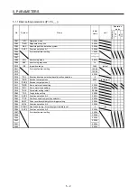

5. PARAMETERS
5 - 14
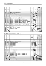
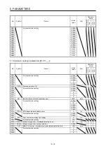
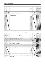
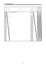
No.
Symbol
Name and function
Initial
value
[unit]
Setting
range
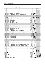
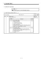
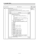
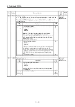
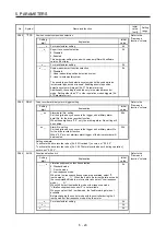
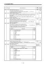
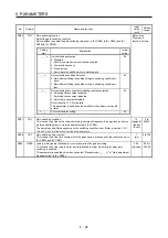
PA08
ATU
Auto tuning mode
Select the gain adjustment mode.
Refer to the
"Name and
function" column.
Setting
digit
Explanation
Initial
value
_ _ _ x
Gain adjustment mode selection
0: 2 gain adjustment mode 1 (interpolation mode)
1: Auto tuning mode 1
2: Auto tuning mode 2
3: Manual mode
4: 2 gain adjustment mode 2
Refer to table 5.2 for details.
1h
_ _ x _
For manufacturer setting
0h
_ x _ _
0h
x _ _ _
0h
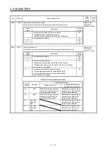
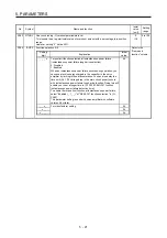
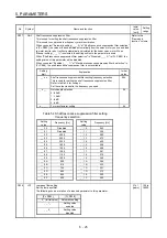
Table 5.2 Gain adjustment mode selection
Setting
value
Gain adjustment
mode
Automatically adjusted parameter
_ _ _ 0
2 gain adjustment
mode 1
(interpolation mode)
[Pr. PB06 Load to motor inertia ratio/load to motor
mass ratio]
[Pr. PB08 Position loop gain]
[Pr. PB09 Speed loop gain]
[Pr. PB10 Speed integral compensation]
_ _ _ 1
Auto tuning mode 1
[Pr. PB06 Load to motor inertia ratio/load to motor
mass ratio]
[Pr. PB07 Model loop gain]
[Pr. PB08 Position loop gain]
[Pr. PB09 Speed loop gain]
[Pr. PB10 Speed integral compensation]
_ _ _ 2
Auto tuning mode 2
[Pr. PB07 Model loop gain]
[Pr. PB08 Position loop gain]
[Pr. PB09 Speed loop gain]
[Pr. PB10 Speed integral compensation]
_ _ _ 3
Manual mode
_ _ _ 4
2 gain adjustment
mode 2
[Pr. PB08 Position loop gain]
[Pr. PB09 Speed loop gain]
[Pr. PB10 Speed integral compensation]
Summary of Contents for MR-J4-100B(-RJ)
Page 17: ...8 MEMO ...
Page 143: ...4 STARTUP 4 20 MEMO ...
Page 199: ...5 PARAMETERS 5 56 MEMO ...
Page 227: ...6 NORMAL GAIN ADJUSTMENT 6 28 MEMO ...
Page 281: ...8 TROUBLESHOOTING 8 16 MEMO ...
Page 303: ...9 DIMENSIONS 9 22 MEMO ...
Page 319: ...10 CHARACTERISTICS 10 16 MEMO ...
Page 429: ...11 OPTIONS AND PERIPHERAL EQUIPMENT 11 110 MEMO ...
Page 435: ...12 ABSOLUTE POSITION DETECTION SYSTEM 12 6 MEMO ...
Page 483: ...14 USING A LINEAR SERVO MOTOR 14 34 MEMO ...
Page 531: ...16 FULLY CLOSED LOOP SYSTEM 16 26 MEMO ...
Page 613: ...17 APPLICATION OF FUNCTIONS 17 82 MEMO ...
Page 654: ...APPENDIX App 41 ...