APPENDIX
App. - 22
App. 5.3 Cautions
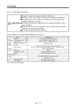
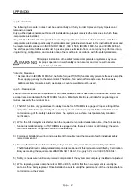
The following basic safety notes must be read carefully and fully in order to prevent injury to persons or
damage to property.
Only qualified personnel are authorized to install, start-up, repair or service the machines in which these
components are installed.
They must be familiar with all applicable local safety regulations and laws in which machines with these
components are installed, particularly the standards and guidelines mentioned in this Instruction Manual and
the requirements mentioned in ISO/EN ISO 13849-1, IEC 61508, IEC/EN 61800-5-2, and IEC/EN 60204-1.
The staff responsible for this work must be given express permission from the company to perform start-up,
programming, configuration, and maintenance of the machine in accordance with the safety standards.
WARNING
Improper installation of the safety related components or systems may cause
improper operation in which safety is not assured, and may result in severe
injuries or even death.
Protective Measures
As described in IEC/EN 61800-5-2, the Safe Torque Off (STO) function only prevents the servo amplifier
from supplying energy to the servo motor. Therefore, if an external force acts upon the drive axis,
additional safety measures, such as brakes or counter-weights must be used.
App. 5.4 Residual risk
Machine manufacturers are responsible for all risk evaluations and all associated residual risks. Below are
residual risks associated with the STO/EMG function. Mitsubishi Electric is not liable for any damages or
injuries caused by the residual risks.
(1) The SS1 function only guarantees the delay time before STO/EMG is engaged. Proper setting of this
delay time is the full responsibility of the company and/or individuals responsible for installation and
commissioning of the safety related system. The system, as a whole, must pass safety standards
certification.
(2) When the SS1 delay time is shorter than the required servo motor deceleration time, if the forced stop
function is malfunctioning, or if STO/EMG is engaged while the servo motor is still rotating; the servo
motor will stop with the dynamic brake or freewheeling.
(3) For proper installation, wiring, and adjustment, thoroughly read the manual of each individual safety
related component.
(4) Be sure that all safety related switches, relays, sensors, etc., meet the required safety standards.
The Mitsubishi Electric safety related components mentioned in this manual are certified by Certification
Body as meeting the requirements of ISO/EN ISO 13849-1 Category 3, PL d and IEC 61508 SIL 2.
(5) Safety is not assured until safety-related components of the system are completely installed or adjusted.
(6) When replacing a servo amplifier etc. or MR-J3-D05, confirm that the new equipment is exactly the
same as those being replaced. Once installed, be sure to verify the performance of the functions before
commissioning the system.
Summary of Contents for MR-J4-100B(-RJ)
Page 17: ...8 MEMO ...
Page 143: ...4 STARTUP 4 20 MEMO ...
Page 199: ...5 PARAMETERS 5 56 MEMO ...
Page 227: ...6 NORMAL GAIN ADJUSTMENT 6 28 MEMO ...
Page 281: ...8 TROUBLESHOOTING 8 16 MEMO ...
Page 303: ...9 DIMENSIONS 9 22 MEMO ...
Page 319: ...10 CHARACTERISTICS 10 16 MEMO ...
Page 429: ...11 OPTIONS AND PERIPHERAL EQUIPMENT 11 110 MEMO ...
Page 435: ...12 ABSOLUTE POSITION DETECTION SYSTEM 12 6 MEMO ...
Page 483: ...14 USING A LINEAR SERVO MOTOR 14 34 MEMO ...
Page 531: ...16 FULLY CLOSED LOOP SYSTEM 16 26 MEMO ...
Page 613: ...17 APPLICATION OF FUNCTIONS 17 82 MEMO ...
Page 654: ...APPENDIX App 41 ...

