


16. FULLY CLOSED LOOP SYSTEM
16 - 22
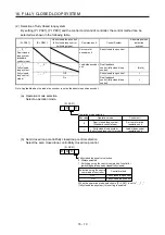
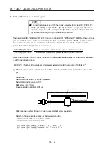
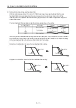
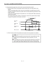
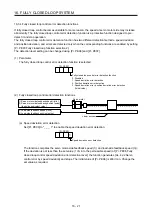
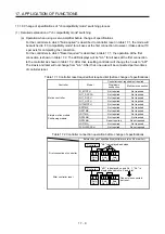
(b) Position deviation error detection
Set [Pr. PE03] to "_ _ _ 2" to enable the position deviation error detection.
Position deviation error detection
2
[Pr. PE03]
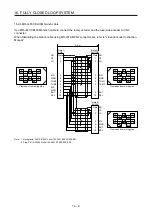
Comparing the servo motor-side feedback position (2)) and load-side feedback position (4)), if the
deviation is not less than the set value (1 kpulses to 20000 kpulses) of [Pr. PE07 Fully closed loop
control position deviation error detection level], the function generates [AL. 42.1 Servo control error
by position deviation] and stops. The initial value of [Pr. PE07] is 100 kpulses. Change the set value
as required.
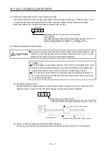
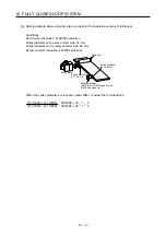
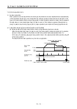
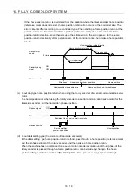
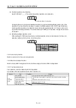
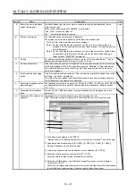
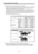
(c) Detecting multiple deviation errors
When setting [Pr. PE03] as shown below, multiple deviation errors can be detected. For the error
detection method, refer to (2) (a), (b) in this section.
[Pr. PE03]
Setting
value
Speed deviation
error detection
Position deviation
error detection
1
2
3
16.3.5 Auto tuning function
Refer to section 6.3 for the auto tuning function.
16.3.6 Machine analyzer function
Refer to Help of MR Configurator2 for the machine analyzer function of MR Configurator2.
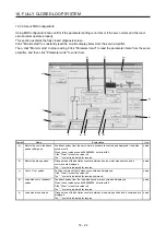
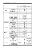
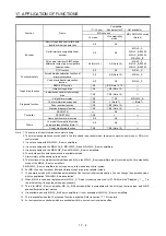
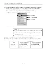
16.3.7 Test operation mode
Test operation mode is enabled by MR Configurator2.
For details on the test operation mode, refer to section 4.5.
Function Item
Usability
Remark
Test
operation
mode
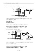
JOG operation
It drives in the load-side encoder resolution unit
Positioning operation
The fully closed loop system is operated in the load-side encoder resolution
unit.
For details, refer to section 4.5.1 (1) (c).
Program operation
Output signal (DO)
forced output
Refer to section 4.5.1 (1) (d).
Motor-less operation
Summary of Contents for MR-J4-100B(-RJ)
Page 17: ...8 MEMO ...
Page 143: ...4 STARTUP 4 20 MEMO ...
Page 199: ...5 PARAMETERS 5 56 MEMO ...
Page 227: ...6 NORMAL GAIN ADJUSTMENT 6 28 MEMO ...
Page 281: ...8 TROUBLESHOOTING 8 16 MEMO ...
Page 303: ...9 DIMENSIONS 9 22 MEMO ...
Page 319: ...10 CHARACTERISTICS 10 16 MEMO ...
Page 429: ...11 OPTIONS AND PERIPHERAL EQUIPMENT 11 110 MEMO ...
Page 435: ...12 ABSOLUTE POSITION DETECTION SYSTEM 12 6 MEMO ...
Page 483: ...14 USING A LINEAR SERVO MOTOR 14 34 MEMO ...
Page 531: ...16 FULLY CLOSED LOOP SYSTEM 16 26 MEMO ...
Page 613: ...17 APPLICATION OF FUNCTIONS 17 82 MEMO ...
Page 654: ...APPENDIX App 41 ...