15. USING A DIRECT DRIVE MOTOR
15 - 12
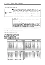
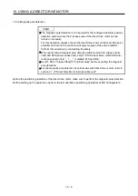
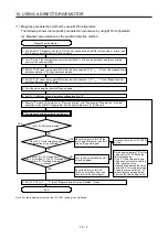
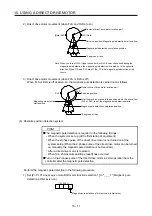
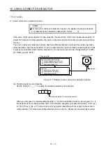
2) Execute the magnetic pole detection. (Refer to (3) (a) in this section.)
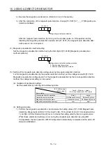
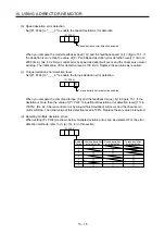
3) After the completion of the magnetic pole detection, change [Pr. PL01] to "_ _ _ 0" (Magnetic pole
detection disabled).
[Pr. PL01]
Magnetic pole detection disabled
0
After the magnetic pole detection, by turning on the Z-phase pulse in JOG operation and by
disabling the magnetic pole detection function with [Pr. PL01], the magnetic pole detection after
each power-on is not required.
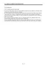
(4) Magnetic pole detection method setting
Set the magnetic pole detection method using the first digit of [Pr. PL08] (Magnetic pole detection
method selection).
[Pr. PL08]
Magnetic pole detection method selection
0: Position detection method
4: Minute position detection method
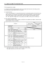
(5) Setting of the magnetic pole detection voltage level by the position detection method
For the magnetic pole detection by the position detection method, set the voltage level with [Pr. PL09
Magnetic pole detection voltage level]. For the magnetic pole detection by the minute position detection
method, the voltage level setting is not required.
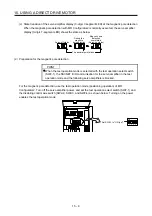
(a) Guideline of parameter settings
Set the parameters by referring to the following table.
[Pr. PL09] setting
(Guide value)
Servo status
Small
←
Medium
→
Large
(10 or less (initial value) 50 or more)
Torques required for operation
Small
Large
Overload, overcurrent alarm
Not frequently occurs
Frequently occurs
Magnetic pole detection alarm
Frequently occurs
Not frequently occurs
Magnetic pole detection accuracy
Low
High
(b) Setting procedure
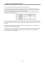
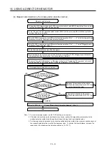
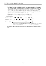
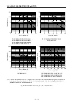
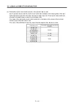
1) Perform the magnetic pole detection, and increase the setting value of [Pr. PL09 Magnetic pole
detection voltage level] until [AL. 50 Overload 1], [AL. 51 Overload 2], [AL. E1 Overload warning
1], and [AL. EC Overload warning 2] occur. Increase the setting value by five as a guide value.
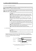
When these alarms and warnings occur during the magnetic pole detection by using MR
Configurator2, the test operation of MR Configurator2 automatically completes and the servo-off
status is established.
Summary of Contents for MR-J4-100B(-RJ)
Page 17: ...8 MEMO ...
Page 143: ...4 STARTUP 4 20 MEMO ...
Page 199: ...5 PARAMETERS 5 56 MEMO ...
Page 227: ...6 NORMAL GAIN ADJUSTMENT 6 28 MEMO ...
Page 281: ...8 TROUBLESHOOTING 8 16 MEMO ...
Page 303: ...9 DIMENSIONS 9 22 MEMO ...
Page 319: ...10 CHARACTERISTICS 10 16 MEMO ...
Page 429: ...11 OPTIONS AND PERIPHERAL EQUIPMENT 11 110 MEMO ...
Page 435: ...12 ABSOLUTE POSITION DETECTION SYSTEM 12 6 MEMO ...
Page 483: ...14 USING A LINEAR SERVO MOTOR 14 34 MEMO ...
Page 531: ...16 FULLY CLOSED LOOP SYSTEM 16 26 MEMO ...
Page 613: ...17 APPLICATION OF FUNCTIONS 17 82 MEMO ...
Page 654: ...APPENDIX App 41 ...

