5. PARAMETERS
5 - 25
No.
Symbol
Name and function
Initial
value
[unit]
Setting
range
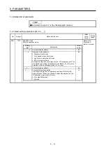
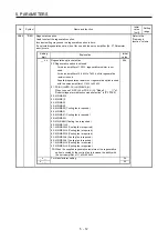
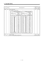
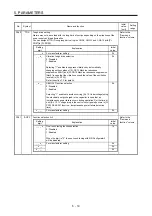
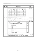
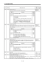
PB17
NHF
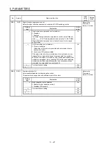
Shaft resonance suppression filter
This is used for setting the shaft resonance suppression filter.
This is used to suppress a low-frequency machine vibration.
When you select "Automatic setting (_ _ _ 0)" of "Shaft resonance suppression filter selection"
in [Pr. PB23], the value will be calculated automatically from the servo motor you use and load
to motor inertia ratio. It will not automatically calculated for the linear servo motor. When
"Manual setting (_ _ _ 1)" is selected, the setting written to the parameter is used.
When "Shaft resonance suppression filter selection" is "Disabled (_ _ _ 2)" in [Pr. PB23], the
setting value of this parameter will be disabled.
When you select "Enabled (_ _ _ 1)" of "Machine resonance suppression filter 4 selection" in
[Pr. PB49], the shaft resonance suppression filter is not available.
Refer to the
"Name and
function" column.
Setting
digit
Explanation
Initial
value
_ _ x x
Shaft resonance suppression filter setting frequency selection
This is used for setting the shaft resonance suppression filter.
Refer to table 5.4 for settings.
Set the value closest to the frequency you need.
00h
_ x _ _
Notch depth selection
0: -40 dB
1: -14 dB
2: -8 dB
3: -4 dB
0h
x _ _ _
For manufacturer setting
0h
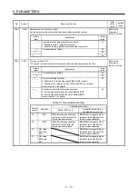
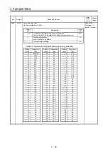
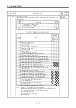
Table 5.4 Shaft resonance suppression filter setting
frequency selection
Setting
value
Frequency [Hz]
Setting
value
Frequency [Hz]
_ _ 0 0
Disabled
_ _ 1 0
562
_ _ 0 1
Disabled
_ _ 1 1
529
_ _ 0 2
4500
_ _ 1 2
500
_ _ 0 3
3000
_ _ 1 3
473
_ _ 0 4
2250
_ _ 1 4
450
_ _ 0 5
1800
_ _ 1 5
428
_ _ 0 6
1500
_ _ 1 6
409
_ _ 0 7
1285
_ _ 1 7
391
_ _ 0 8
1125
_ _ 1 8
375
_ _ 0 9
1000
_ _ 1 9
360
_ _ 0 A
900
_ _ 1 A
346
_ _ 0 B
818
_ _ 1 B
333
_ _ 0 C
750
_ _ 1 C
321
_ _ 0 D
692
_ _ 1 D
310
_ _ 0 E
642
_ _ 1 E
300
_ _ 0 F
600
_ _ 1 F
290
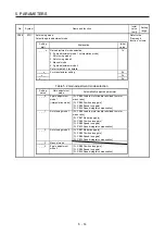
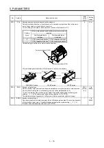
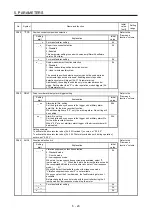
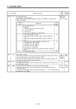
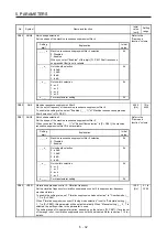
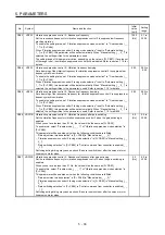
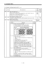
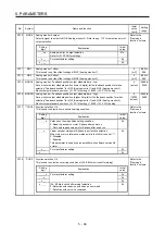
PB18
LPF
Low-pass filter setting
Set the low-pass filter.
The following shows a relation of a required parameter to this parameter.
3141
[rad/s]
100 to
18000
[Pr. PB23]
[Pr. PB18]
_ _ 0 _ (Initial value)
Automatic setting
_ _ 1 _
Setting value
enabled
_ _ 2 _
Setting value
disabled
Summary of Contents for MR-J4-100B(-RJ)
Page 17: ...8 MEMO ...
Page 143: ...4 STARTUP 4 20 MEMO ...
Page 199: ...5 PARAMETERS 5 56 MEMO ...
Page 227: ...6 NORMAL GAIN ADJUSTMENT 6 28 MEMO ...
Page 281: ...8 TROUBLESHOOTING 8 16 MEMO ...
Page 303: ...9 DIMENSIONS 9 22 MEMO ...
Page 319: ...10 CHARACTERISTICS 10 16 MEMO ...
Page 429: ...11 OPTIONS AND PERIPHERAL EQUIPMENT 11 110 MEMO ...
Page 435: ...12 ABSOLUTE POSITION DETECTION SYSTEM 12 6 MEMO ...
Page 483: ...14 USING A LINEAR SERVO MOTOR 14 34 MEMO ...
Page 531: ...16 FULLY CLOSED LOOP SYSTEM 16 26 MEMO ...
Page 613: ...17 APPLICATION OF FUNCTIONS 17 82 MEMO ...
Page 654: ...APPENDIX App 41 ...

