


17. APPLICATION OF FUNCTIONS
17 - 72
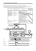
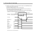
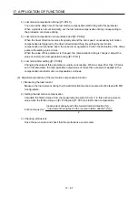
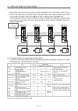
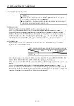
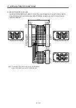
(4) Rotation direction setting
Rotation directions can be different among a controller command, master axis, and slave axes. To align
the directions, set [Pr. PA14] referring to (4) in this section. Not doing so can cause such as an overload
due to a reverse direction torque against machine system rotation direction.
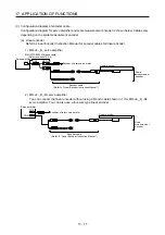
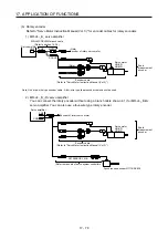
Controller
Master axis
Slave axis 1
Slave axis 2
Slave axis 3
Position control
Speed control
S
Current control
+
-
-
Current control
Current control
Current control
[Pr. PA14]
0 or 1 (Note)
[Pr. PA14]
0 or 1 (Note)
[Pr. PA14]
0 or 1 (Note)
[Pr. PA14]
0 or 1 (Note)
+
-
+
-
+
-
+
-
+
POL
POL
POL
POL
Note. Setting "1" will reverse the polarity.
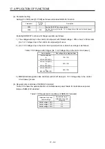
Fig. 17.3 Rotation direction setting of master and slave axes with torque command method for an
example of one master axis and three slave axes
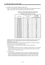
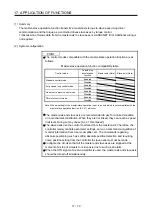
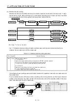
Table 17.11 Rotation direction setting parameter
No.
Symbol
Name and function
PA14 *POL Rotation direction selection
1. For master axis
Select a servo motor rotation direction of master axis to SSCNET controller command.
0: Servo motor CCW rotation in positioning address increase direction
1: Servo motor CW rotation in positioning address increase direction
2. For slave axis
Select servo motor rotation direction to a command from master axis.
0: Torque command polarity from master axis
1: Reverse of torque command polarity from master axis
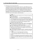
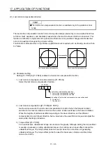
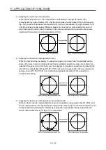
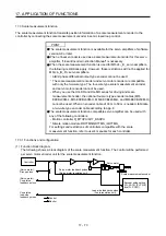
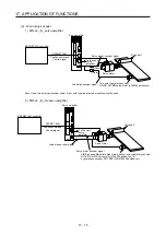
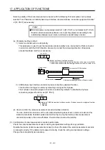
The following shows a setting example of rotation direction for a platform truck with one master axis and
three slave axes.
To set a rotation direction of the servo motor according to the moving direction, set the torque command
polarity to the slave axis 1 the same as that to the master axis, and set the opposite polarity to the slave
axis 2 and slave axis 3 from the master axis.
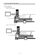
Slave axis 2
Slave axis 1
Master axis
Slave axis 3
Moving direction
CW
CCW
CCW
CW
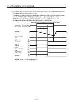
[Pr. PA14] setting
Axis [Pr.
PA14]
Master axis
0
Slave axis 1
0
Slave axis 2
1
Slave axis 3
1
Summary of Contents for MR-J4-100B(-RJ)
Page 17: ...8 MEMO ...
Page 143: ...4 STARTUP 4 20 MEMO ...
Page 199: ...5 PARAMETERS 5 56 MEMO ...
Page 227: ...6 NORMAL GAIN ADJUSTMENT 6 28 MEMO ...
Page 281: ...8 TROUBLESHOOTING 8 16 MEMO ...
Page 303: ...9 DIMENSIONS 9 22 MEMO ...
Page 319: ...10 CHARACTERISTICS 10 16 MEMO ...
Page 429: ...11 OPTIONS AND PERIPHERAL EQUIPMENT 11 110 MEMO ...
Page 435: ...12 ABSOLUTE POSITION DETECTION SYSTEM 12 6 MEMO ...
Page 483: ...14 USING A LINEAR SERVO MOTOR 14 34 MEMO ...
Page 531: ...16 FULLY CLOSED LOOP SYSTEM 16 26 MEMO ...
Page 613: ...17 APPLICATION OF FUNCTIONS 17 82 MEMO ...
Page 654: ...APPENDIX App 41 ...